
User manual
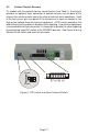
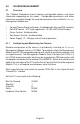

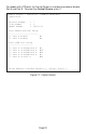

The Module Screen (DIP-switch control shown) provides general information
concerning the configuration and status of the module. The screen displays
the model and serial numbers, hardware and software revisions, as well as the
condition of the LEDs, Alarm Indicators and DIP-switches. The DIP-switches
1 - 4 correspond with the physical switches on the back of the chassis. These
switches can be changed from the Module Screen by selecting the appropriate
switch number. DIP-switches 9 - 15 can only by configured from the Module
Screen options. Select the appropriate option to change the DIP-switch setting.
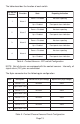
Module Screen - iConverter 1-Module Redundant
Identifier -
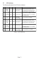
Switch ON Condition OFF Condition H/W Actual
1: Alarm 1 Enable Alarm 1 Disable On On
2: Alarm 2 Enable Alarm 2 Disable Off Off
3: Alarm 3 Enable Alarm 3 Disable Off Off
4: Alarm 4 Enable Alarm 4 Disable Off Off
5: Not Available
6: Not Available
7: Not Available
8: Not Available
Soft Switch ON Condition Off Condition State
9: Port A Manual Port A AN Mode Off
10: Port A 10 Mbps Port A 100 Mbps Off
11: Port A HDX Port A FDX Off
12: Port B Manual Port B AN Mode Off
13: Port B 10 Mbps Port B 100 Mbps Off
14: Port B HDX Port B FDX Off
15: Pause Enabled Pause Disabled Off
16: Not Available
Toggle Switch(1-16), ....... (S)tatus, Port(C)tl >
Figure 10: Module Screen - Showing DIP-switches Only
Page 18