BEDIENUNGSANLEITUNG USER MANUAL MP SERIES PA AMPLIFIER Für weiteren Gebrauch aufbewahren! Keep this manual for future needs! © Copyright Nachdruck verboten! Reproduction prohibited!
Inhaltsverzeichnis/ Table of contents 1. EINFÜHRUNG ............................................................................................................................................... 4 2. SICHERHEITSHINWEISE............................................................................................................................. 4 3. RECHTLICHE HINWEISE............................................................................................................................. 6 3.
BEDIENUNGSANLEITUNG ELA-Verstärker Lesen Sie vor der ersten Inbetriebnahme zur eigenen Sicherheit diese Bedienungsanleitung sorgfältig durch! Alle Personen, die mit der Aufstellung, Inbetriebnahme, Bedienung, Wartung und Instandhaltung dieses Gerätes zu tun haben, müssen - entsprechend qualifiziert sein - diese Bedienungsanleitung genau beachten - die Bedienungsanleitung als Teil des Produkts betrachten - die Bedienungsanleitung während der Lebensdauer des Produkts behalten - die Bedienungsanleitung an jed
Der Aufbau entspricht der Schutzklasse I. Der Netzstecker darf nur an eine Schutzkontakt-Steckdose angeschlossen werden, deren Spannung und Frequenz mit dem Typenschild des Gerätes genau übereinstimmt. Ungeeignete Spannungen und ungeeignete Steckdosen können zur Zerstörung des Gerätes und zu tödlichen Stromschlägen führen. Den Netzstecker immer als letztes einstecken. Der Netzstecker muss dabei gewaltfrei eingesetzt werden. Achten Sie auf einen festen Sitz des Netzsteckers.
Bevor das Gerät eingeschaltet wird, müssen alle Fader und Lautstärkeregler auf Null bzw. auf Minimum gestellt werden. ACHTUNG: Endstufen immer zuletzt einschalten und zuerst ausschalten! Kinder und Laien vom Gerät fern halten! GESUNDHEITSRISIKO! Beim Betreiben einer Beschallungsanlage lassen sich Lautstärkepegel erzeugen, die zu irreparablen Gehörschäden führen können. Im Geräteinneren befinden sich keine zu wartenden Teile.
3.1 Kleine Hörkunde Immer mehr junge Menschen leiden unter einem Hörverlust von 25 Dezibel und mehr, überwiegend hervorgerufen durch laute Musik von tragbaren Kassetten- und CD-Abspielgeräten oder in der Diskothek. Wer Musik über Beschallungsanlagen wiedergibt, sollte wissen, welchen Schallpegeln er sein Gehör und das des Publikums aussetzt. Sie erreichen im zeitlichen Mittel ohne weiteres 75 bis 105 dB(A) in der Disco bzw. 95 bis 115 dB(A) bei einem Rockkonzert.
4. BESTIMMUNGSGEMÄSSE VERWENDUNG Die ELA-Mono-Mischverstärker der MP-Serie sind speziell für den Einsatz in ELA-Beschallungsanlagen konzipiert. Es stehen Ausgänge für ELA-Lautsprecher mit 70-V- und 100-V-Audioübertrager oder 4-16- Lautsprecher Verfügung. An die sechs mischbaren Eingänge können drei Mikrofone und drei Geräte mit Line-Pegel angeschlossen werden.
5. GERÄTEÜBESCHREIBUNG 5.
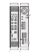
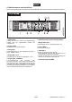
5.2 Bedienelemente und Anschlüsse Diese Anleitung beschreibt exemplarisch das Modell MP-250. Die anderen Modelle sind ähnlich konstruiert. 1 Netzschalter Schaltet das Gerät ein und aus. Die Betriebsanzeige POWER zeigt den eingeschalteten Zustand des Verstärkers an. 2 Regler LEVEL 6 LED-Pegelanzeige für das Ausgangssignal 7 Regler LINE 1 bis 3 Lautstärkeregler für die Line-Eingänge LINE 1 bis 3. 8 Taste CHIME Masterregler für die Gesamtlautstärke. Zum Auslösen des Gongs.
Regler PRIORITY LEVEL Regelt den Pegel der Absenkung bei Auslösen des Gongs und bei einer Mikrofondurchsage über Mikrofonkanal 3. 12 Eingänge MIC 1 und MIC 2 6,3-mm-Klinkenbuchsen dynamischen Mikrofonen. zum Anschluss von 15 Schraubanschlüsse für 70-V- und 100-VLautsprecher 16 Schraubanschluss für 4- bis 16- -Lautsprecher 17 Gemeinsamer Masseanchluss COM für alle Lautsprecher 18 Netzkabel 13 Eingänge LINE 1 bis 3 Zum Anschluss an eine Steckdose.
6. INSTALLATION Diese Endstufe ist für ein 483-mm-Rack (19") vorgesehen. Bei dem Rack sollte es sich um ein „DoubleDoor-Rack“ handeln, an dem sich sowohl die Vorder- als auch die Rückseite öffnen lassen. Das Rackgehäuse sollte mit einem Lüfter versehen sein. Achten Sie bei der Standortwahl der Endstufe darauf, dass die warme Luft aus dem Rack entweichen kann und genügend Abstand zu anderen Geräten vorhanden ist. Dauerhafte Überhitzung kann zu Schäden an der Endstufe führen.
Hinweise zur Auswahl geeigneter Lautsprecherkabel beim Einsatz von niederohmigen Lautsprechern • Lautsprecherboxen dürfen nur über ausreichend dimensionierte Kabel angeschlossen werden. Zu schwach dimensionierte Kabel führen zu einer Erhitzung der Kabel und zu enormen Leistungsverlusten und Klangverschlechterungen. • Wir empfehlen für alle Lautsprecherboxen bis 400 Watt einen Kabeldurchmesser von 2,5 mm², für alle höheren Leistungen 4 mm².
8. BEDIENUNG 1. Schalten Sie zunächst alle anderen Geräte der ELA-Anlage ein, um laute Schaltgeräusche zu vermeiden. 2. Stellen Sie vor dem Einschalten den Masterregler LEVEL und die Lautstärkeregler der Eingangskanäle auf Null, um zu Anfang eine zu hohe Lautstärke zu vermeiden. Schalten Sie dann den Verstärker mit dem Netzschalter ein. Die Betriebsanzeige POWER leuchtet. 3. Drehen Sie den Masterregler LEVEL so weit auf, dass das Mischungsverhältnis der Signalquellen optimal eingestellt werden kann. 4.
9. PROBLEMBEHEBUNG PROBLEM Gerät lässt anschalten. URSACHE LÖSUNG nicht • Die Netzleitung ist nicht ange- • Überprüfen Sie die Netzleitung schlossen. und eventuelle Verlängerungsleitungen. Kein Signal. • Die Anschlussleitung des ent- • Überprüfen Sie die Anschlusssprechenden Gerätes ist nicht leitung und ob die Stecker fest in richtig oder überhaupt nicht angeden Buchsen sitzen. schlossen bzw. ist defekt. • Die Anschlussbuchse oder der • Reinigen Sie die Buchse und/oder Stecker sind schmutzig. den Stecker.
11.
USER MANUAL PA Amplifier CAUTION! Keep this device away from rain and moisture! Unplug mains lead before opening the housing! For your own safety, please read this user manual carefully before you initially start-up.
Please make sure that there are no obvious transport damages. Should you notice any damages on the A/C connection cable or on the casing, do not take the device into operation and immediately consult your local dealer. This device falls under protection-class I. The power plug must only be plugged into a protection class I outlet. The voltage and frequency must exactly be the same as stated on the device.
CAUTION: Turn the amplifier on last and off first! Please note that damages caused by manual modifications on the device or unauthorized operation by unqualified persons are not subject to warranty. Keep away children and amateurs! HEALTH HAZARD! By operating an amplifying system, you can produce excessive sound pressure levels that may lead to permanent hearing loss. There are no serviceable parts inside the device. Maintenance and service operations are only to be carried out by authorized dealers. 3.
Overview on the different noise levels 10 dB Heartbeat 20 - 30 dB Whisper 80 dB Heavy traffic or telephone ringing 40 dB Average home 100 dB Power mower 50 dB Light traffic 120 dB Boom box in car 60 dB Normal conversation 130 dB Pain level 70 dB Vacuum cleaner 140 dB Jet plane 30 meters overhead 90 dB Pneumatic drill It is important to know that doubling the power increases the noise level by 3 dB.
shocks. When using smoke machines, make sure that the device is never exposed to the direct smoke jet and is installed in a distance of 0.5 meters between smoke machine and device. The ambient temperature must always be between -5° C and +45° C. Keep away from direct insulation (particularly in cars) and heaters. The relative humidity must not exceed 50 % with an ambient temperature of 45° C. This device must only be operated in an altitude between -20 and 2000 m over NN.
5.2 Operating elements and connections This user manual describes the MP-250 as a reference. The other models are similar in construction. 1 Power on/off Turns the unit on and off. The power indicator lights up when the unit is powered on. 6 LED level meter for the output signal 7 Controls LINE 1 to 3 Volume controls for the line inputs LINE 1 to 3. 2 Control LEVEL Master control for the total volume. 8 Button CHIME For releasing the chime.
11 Control PRIORITY LEVEL 16 Screw connector for 4 to 16 speakers Adjusts the attenuation level when releasing the chime and in case of microphone announcements via microphone channel 3. 17 Common ground connection COM for all speakers 12 Inputs MIC 1 and MIC 2 18 Mains cable 6.3 mm jacks for connecting dynamic microphones. For connection to a mains outlet. 13 Inputs LINE 1 to 3 Stereo RCA inputs for connecting units with line level (e.g. CD player).
6. INSTALLATION This amplifier is built for 483 mm racks (19"). This rack should be a double-door rack where front panel and rear panel can be opened. The rack should be provided with a cooling fan. When mounting the amplifier into the rack, please make sure that there is enough space around the device so that the heated air can be passed on. Steady overheating will damage your device. You can fix the amplifier with four screws M6 in the rack.
General information on installing cables • Always treat cables carefully and protect them from damages during transportation. • Install cables always in a structured way and protect them from damage. • Cables must be installed in a way that no person can stumble over them. Always fix cables with an appropriate tape. • Cables should be installed directly (no loops, S-shaped overlengths). • Always install cables far away from power cables (never closely parallel).
8. OPERATION 1. To prevent loud switching noise, first switch on all other units of the PA system. 2. Prior to switching on, turn the master control LEVEL and the level controls of the input channels to zero to avoid a high volume at the beginning. Then switch on the unit with the power switch. The power indicator lights up. 3. Turn up the master control LEVEL so that the mixing ration of the signal sources can be adjusted in an optimum way. 4.
9. PROBLEM CHART PROBLEM No power. • No sound. • • Fan does not work, LEDs • do not light up. LED FAULT lights up • permanently. • • • • CAUSE The power cord is not connected. REMEDY Check the power cord and any extension cables. The power cord of the respective • Check the power cord and if the device is not connected properly or plugs are tightly connected with the not connected at all or is defective. sockets. The connection socket or the plug is • Clean the socket and/or the plug. dirty.
11. TECHNICAL SPECIFICATIONS MP-60 Power supply: Output power: Output type: Microphone input: Line input: Output: Frequency range: Distortion: S/N ratio: Protection: Indicators: Dimensions: Weight: MP-120 230 V AC, 50 Hz ~ 60 W RMS 120 W RMS 70 V, 100 V or 4-16 5 mV, 600 300 mV, 10 k screw connectors 80 Hz - 14 kHz 0.5 % (1 kHz) 85 dB (line), 75 dB (mic) over current, short circuit, turn-on delay power, fault, level 483 x 400 x 88 mm 8.5 kg 9.