
User's Manual


V740 RFID READER/WRITER, ANTENNA 2005-09, REV0.1
OPERATION MANUAL
10 of 56 ©OMRON CORPORATION 2005
1.3 Reader Installation
The following parts are provided with the reader:
Part Qty. Part Number
V740-Reader/Writer 1 V740-BA50C22A-US
Power Supply 1 -
1.3.1 Install the Reader
You can place the reader on a shelf or mount it to a
wall. Mounting shelf and wall should be flat to fix the
reader securely.
To mount the reader on a wall:
1. Hold the reader in its four mounting location and
mark the position of the mounting screws
2. Drill holes for the screws and install wall anchors if
required. Be sure anchors must have enough
strength to fixed the reader against vibration.
3. Insert the M5x16 screws with spring washers and
flat washers and tighten until almost flush with the
wall.
4. Slip the reader over the screws and slide down to
lock the screws in the keyhole openings.
5. Tighten the screws securely.
6. Fix the AC adaptor so that not to move by
vibration and tense DC plug cables. Do not bundle
the adaptor cable with other signal or power lines.
Mechanical Loading - Mounting of the equipment in
the rack should be such that a hazardous condition is
not achieved due to uneven mechanical loading.
1.3.2 Install the Antennas
The antennas can be mounted directly to a variety of
surfaces. Mounting surfaces should be flat to fix the
antenna securely.
To mount the reader on a wall :
1. Hold the antenna in its mounting location and
mark the position of the mounting screws with
minimum (4) points. The antenna has several
mounting holes for each side. Choose 4 of those
with diagonal position according to the mounting
location.
Drill holes for the screws and install wall anchors if
required.
2. Insert the M4x20 screws with spring washers and
flat washers and tighten until almost flush with the
wall.
3. Tighten the screws securely.
Note: For best performance, mount the antenna in
the horizontal orientation as pictured above.
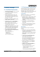
1.3.3 Connect the Reader
A B C D E
A = RJ-45 Ethernet port 10/100Base-T
B = Safe Mode button
C = RS232C (Do not use)
D = I/O port (Non LPS)
E = DC power input
Note: MAC Address is displayed on the lower part of
RJ-45 Ethernet port.
Mountin
g
holes
Mountin
g
holes