MEMS Flow Sensors D6F series Series Catalog Faster and more accurate than ever before MEMS flow sensor : the ideal means for mass flow measurement Omron flow sensor so precise even the flap of a butterfly’s wings will not be missed.
Realizing a highly accurate flow measurement, Omron’s MEMS flow sensor accurately detects minute airflow so much as a single flap of a butterfly’s butterfly butterf y s wings. win ngs. A gas flow sensor capable of “measuring mass flow” independent of temperature and pressure. re. D6F-A6 D6F-W Mass Flow Measurement Q1 There are two balloons; each having different volumes. But these balloons have the same mass. Why is that? A The volume increases/decreases according to the pressure and temperature changes.
sensing even a single flap of a butterfly’s wings Operating characteristic Error Output voltage (V) Standard lower limit -4% -6% 0 4 6 Magnified 5 view 1.04 4 3 1.02 2 1 1.00 0 -0.2 0.0 0.2 0.4 0.6 0.8 1.0 Flow rate(SLM) Flow rate of 1L: Output corresponding to flow rate change below 1/1000 of full scale.
Applications Omron flow sensors cover wide range of applications and can be used for different purposes. Application Examples Clogging Detection For monitoring the flow of the cooling air to optimize the cooling efficiency and avoid malfunctions.
Selection of Products Select the most suitable sensor from many variations.
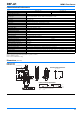
List of D6F series MEMS Flow Sensor Air Minute flow Analog Air Applicable gas Items Model D6F-01A1-110 D6F-P0010A D6F-P0010AM2 D6F-P0001A1 D6F-02A1-110 D6F-03A3-000 Shape 5 4 0〜3L/min 3 Flow rate range (L/mim) 0〜2L/min 2 1 0〜0.
MEMS 2-axis flow sensor/ MEMS flow sensor Air Flow velocity Analog Digital type only Digital Applicable gas Items Air Model D6F-D D6F-W01A1 D6F-V03A1 D6F-W04A1 D6F-W10A1 Shape 0〜10m/s 10 8 Flow velocity range (m/s) 6 4 2 -1〜1m/s 0〜1m/s 35 31 0〜3m/s 0〜4m/s 33 31 0 -2 Page 31 MEMS differential pressure sensor Air Differential pressure Digital Digital type only Applicable gas Items Model Air D6F-PH0505AD3 D6F-PH0025AD1 D6F-PH5050AD3 Shape 500 250 Differential pressure
D6F-A1 MEMS Flow Sensor A Compact, High-accuracy Sensor That Measures Low Flow Rates. • High accuracy of ±3% FS. • Flow rates can be measured without being affected by temperature or pressure. RoHS Compliant Refer to the Common Precautions for the D6F Series on page 40. Ordering Information Output Voltage Characteristics MEMS Flow Sensor D6F-01A1-110 0 to 1 L/min Air 0 to 2 L/min 6.0 6.0 D6F-01A1-110 5.0 5.
D6F-A1 MEMS Flow Sensor Characteristics/Performance Model D6F-01A1-110 Flow Range (See note 1.) D6F-02A1-110 0 to 1 L/min 0 to 2 L/min. Calibration Gas (See note 2.) Air Flow Port Type Bamboo joint Maximum outside diameter: 8.6 mm, Minimum outside diameter: 7.4 mm Electrical Connection Three-pin connector Power Supply 10.8 to 26.
D6F-N2/-L2 MEMS Flow Sensor A Compact, High-accuracy Sensor That Measures Low Flow Rates. • High accuracy of ±3% FS. • Flow rates can be measured without being affected by temperature or pressure. RoHS Compliant Refer to the Common Precautions for the D6F Series on page 40. on page 40. Ordering Information Output Voltage Characteristics MEMS Flow Sensor D6F-01N2-000 Natural gas (13A) LP gas 6.0 6.0 0 to 1 L/min D6F-01N2-000 5.0 5.0 0 to 5 L/min D6F-05N2-000 0 to 2 L/min D6F-02L2-000 4.0 3.
D6F-N2/-L2 MEMS Flow Sensor Characteristics/Performance Model D6F-01N2-000 Flow Range (See note 1.) D6F-05N2-000 0 to 1 L/min Calibration Gas (See note 2.) Natural gas (13A) Flow Port Type Rc 1/4 thread Electrical Connection Three-pin connector Power Supply 10.8 to 26.4 VDC 0 to 2 L/min. Propane gas Current Consumption 15 mA max.
D6F-A3 MEMS Flow Sensor High-accuracy Sensing with a Thin, Compact Body. • A thin, lightweight flow sensor. • Unique flow path structure provides high precision and fast response. RoHS Compliant Refer to the Common Precautions for the D6F Series on page 40. Ordering Information Output Voltage Characteristics MEMS Flow Sensor D6F-03A3-000 Flow rate range Air 0 to 3 L/min Model 6.0 D6F-03A3-000 5.
D6F-A3 MEMS Flow Sensor Characteristics/Performance Model D6F-03A3-000 Flow Range (See note 1.) 0 to 3 L/min Calibration Gas (See note 2.) Air Flow Port Type M5 thread Electrical Connection Three-pin connector Power Supply 10.8 to 26.4 VDC Current Consumption 15 mA max. with no load, with a Vcc of 12 to 24 VDC, and at 25°C Output Voltage 1 to 5 VDC (non-linear output, load resistance of 10 kΩ) Accuracy ±5% FS (25°C characteristic) Repeatability (See note 3.) ±0.
D6F-A5 MEMS Flow Sensor High-accuracy Sensing with a Compact Body for Flow Rates Up to 50 L/min. • Accurately detects a mass flow rate of 10 to 50 L/min. • A compact size of 30 × 78 × 30 mm (H × W × D). RoHS Compliant Refer to the Common Precautions for the D6F Series on page 40.
D6F-A5 MEMS Flow Sensor Characteristics/Performance Model D6F-10A5-000 Flow Range (See note 1.) D6F-20A5-000 0 to 10 L/min 0 to 20 L/min Calibration Gas (See note 2.) Air Flow Port Type Manifold Electrical Connection Three-pin connector Power Supply 10.8 to 26.4 VDC Current Consumption 15 mA max. with no load, with a Vcc of 12 to 24 VDC, and at 25°C Output Voltage 1 to 5 VDC (non-linear output, load resistance of 10 kΩ) Accuracy ±3% FS (25°C characteristic) Repeatability (See note 3.
D6F-A6 MEMS Flow Sensor High-accuracy Sensing with a Compact Body for Flow Rates up to 50 L/min. • Accurately measures an air mass flow rate of 10 to 50 L/min. • A compact size of 30 × 78 × 30 mm (H × W × D). RoHS Compliant Refer to the Common Precautions for the D6F Series on page 40. Ordering Information Output Voltage Characteristics MEMS Flow Sensor Rc 1/4 thread Air NPT 1/8 thread Flow rate range D6F-10A6-000 6.0 6.0 D6F-20A6-000 5.0 5.
D6F-A6 MEMS Flow Sensor Characteristics/Performance Model D6F-10A6-000 Flow Range (See note 1.) D6F-20A6-000 0 to 10 L/min 0 to 20 L/min Calibration Gas (See note 2.) Air Flow Port Type Rc 1/4 thread Electrical Connection Three-pin connector D6F-50A6-000 0 to 50 L/min D6F-10A61-000 0 to 10 L/min 10.8 to 26.4 VDC Current Consumption 15 mA max. with no load, with a Vcc of 12 to 24 VDC, and at 25°C Output Voltage 1 to 5 VDC (non-linear output, load resistance of 10kΩ min.
D6F-A7/-L7/-N7 MEMS Flow Sensor Reduction of Piping time by quick joint connection • Low -flow rate of natural gas and LP gas can be measured. • 10 L/min and 30 L/min of Air can be measured. • Compact size of 30 × 84.6 × 30 mm (H × W × D). RoHS Compliant Refer to the Common Precautions for the D6F Series on page 40.
D6F-A7/-L7/-N7 MEMS Flow Sensor Characteristics/Performance Model D6F-05N7-000 D6F-02L7-000 D6F-10A7-000 Flow Range (See note 1.) 0 to 5 L/min 0 to 2 L/min 0 to 10 L/min Calibration Gas (See note 2.) Natural gas (13A) LP gas Air Flow Port Type Quick joint P10 Electrical Connection Three-pin connector Power Supply 10.8 to 26.4 VDC Current Consumption 15 mA max.
D6F-A7D/-AB71D MEMS Flow Sensor Digital Compensation for High Accuracy • Temperature compensation and linear compensation produce high accuracy (±3% RD (25% to 100% FS)). • Compact models for 10 to 70 L/min. • Reduced piping work with quick-fastening feature. RoHS Compliant Refer to the Common Precautions for the D6F Series on page 40.
D6F-A7D/-AB71D MEMS Flow Sensor Characteristics/Performance Model D6F-10A7D-000-0 Flow Range (See note 1.) 0 to 10L/min D6F-20A7D-000-0 0 to 20 L/min D6F-50A7D-000-0 0 to 50 L/min Calibration Gas (See note 2.) Air Flow Port Type Quick joint P10 Electrical Connection Four-pin connector Power Supply 3.0 to 3.6 VDC Current Consumption 10 mA max. with no load, Vcc = 3.3 VDC, GND = 0 VDC, 25°C Quick joint P14 Resolution 15 bit Accuracy (See note 3.) ±5%RD (10%F.S. ≤ Flow rate < 25%F.S.
D6F-A7D/-AB71D MEMS Flow Sensor Dimensions (Unit: mm) ● MEMS Flow Sensors D6F-10A7D-000-0 D6F-20A7D-000-0 D6F-50A7D-000-0 Lot No. Display A Recommended Quick joint male P10 type 9 max. A 1.6 max 2.5±0.05 2 min. (4.4) 84.6±0.5 X X 2 min. R0.4 R0.4 (60.6) (66.6) 10 +0 -0.05 dia. 17 dia. 20 dia. max. 12.85±0.05 dia. C0.1 (34.9) Y B 2.5 C0.3 +0.25 -0 C0.5 CROSS X-X B If using a Rc3/8 converter joint, the following is recommended. REGAL JOINT CO., LTD eigyou@rgl.co.
D6F-AB71 MEMS Flow Sensor Reduction of Piping time by quick joint connection • Reduce the influence of pulsation flow by bypass flow path • 30 L/min and 70 L/min of Air can be measured. • Compact size of 30 × 84.6 × 32 mm (H × W × D). RoHS Compliant Refer to the Common Precautions for the D6F Series on page 40.
D6F-AB71 MEMS Flow Sensor Characteristics/Performance Model D6F-30AB71-000 Flow Range (See note 1.) D6F-70AB71-000 0 to 30 L/min 0 to 70 L/min Calibration Gas (See note 2.) Air Flow Port Type Quick joint P14 Electrical Connection Three-pin connector Power Supply 10.8 to 26.4 VDC Current Consumption 15 mA max. with no load and Vcc of 12 to 24 VDC, GND = 0 VDC, 25°C Output Voltage 1 to 5 VDC (non-linear output, load resistance of 10 kΩ min.) Accuracy ±3%F.S.
D6F-P MEMS Flow Sensor A Compact, High-accuracy Flow Sensor with Superior Resistance to Environments. • Anti-dust performance is improved using the Cyclon method. • A full lineup of models with different connector types: bamboo joints, lead terminals for direct mounting on-board, and manifolds. • High accuracy of ±5% FS. RoHS Compliant Refer to the Common Precautions for the D6F Series on page 40. Ordering Information MEMS Flow Sensor Flow Port Type Connection Applicable fluid Flow rate range 0 to 0.
D6F-P MEMS Flow Sensor Characteristics/Performance Model D6F-P0001A1 Flow Range (See note 1.) 0 to 0.1 L/min Calibration Gas (See note 2.) Air D6F-P0010A1 D6F-P0010A2 Bamboo joint Flow Port Type Maximum outside diameter: 4.9 mm, minimum outside diameter: 4.0 mm Electrical Connection Lead terminals Power Supply 4.75 to 5.25 VDC Current Consumption 15 mA max. with no load and a Vcc of 5.0 V 0.5 to 2.
D6F-P MEMS Flow Sensor Connections/Dimensions (Unit: mm) ● Lead Terminals Label: Gives model and lot numbers. D6F-P0001A1/D6F-P0010A1 Two, 3-dia. through hole 10 23.3 Two, 4.9 dia. 2.6 dia. 11.7 7.2 Two, 1.1 dia. 4.76 Three, 1.3-dia. lands Label 2.54 MADE IN JAPAN D6F 27.2 7.3 13.5 Three, 0.8-dia. through holes 5.04 7.6±0.2 14 Recommended Dimensions for Connector Mounting Holes (Bottom view) 16.2 6 1.2 1.7 17.2 13.5 1.5 Two, R: 1.4 Connector XG8V-0344 (manufactured by OMRON) A 9.
D6F-PH MEMS Differential pressure Sensor A Compact, High-accuracy Differential Pressure Sensor with Superior Resistance to Environments. • High accuracy of ±3% RD • Linearized and temperature compensated • Digital output (I2C communication) • High flow impedance to reduce the influence of bypass configuration • Lineup of 4 types of slave address models RoHS Compliant Refer to the Common Precautions for the D6F Series on page 40. Ordering Information Applicable fluid (See note 1.
D6F-PH MEMS Differential pressure Sensor Characteristics/Performance Model D6F-PH0025AD1-@ Differential pressure range (See note 1) 0 to 250 Pa D6F-PH0505AD3-@ ±50 Pa D6F-PH5050AD3-@ ±500 Pa Calibration Gas (See note 2.) Air Port Type Bamboo joint, Maximum outside diameter: 4.9 mm, minimum outside diameter: 4.0 mm Power Supply 2.3 to 3.6 VDC Current Consumption 6 mA max. with no load and Vcc of 3.3 VDC, GND = 0 VDC, 25°C Resolution 12 bit Zero point tolerance (See note 3.) ±0.
D6F-PH MEMS Differential pressure Sensor Connections/Dimensions (Unit: mm) 18 7.05 High pressure side 26 Mounting Direction Install the Sensor so that the joints are facing upward. 20 16.5 10 Low pressure side Two, through hole 2 dia 22 Two, 4 dia. Recommendation size for pin header installation (tolerrances: ±0.1) Two, 4.9 dia 6.5 Two, 4 dia. 12 10.5 Two, through h Two, through ole 2.2 dia hole 2 dia. 4 16.5 10.3 5 Two, R2 3.35 (2.6) Pin Header (3.7) Four, 0.48 dia. Three, 2 5.
D6F-W MEMS Flow Sensor A Compact Sensor That Uses OMRON’s Unique Flow Path Structure for High-performance Flow Rate Measurement. • Anti-dust performance enhanced by OMRON’s unique three-dimensional flow path structure. • High accuracy of ±5% FS. RoHS Compliant Refer to the Common Precautions for the D6F Series on page 40. Output Voltage Characteristics Applicable fluid Flow rate range 0 to 1 m/s Air Model D6F-W01A1 0 to 4 m/s D6F-W04A1 0 to 10 m/s D6F-W10A1 D6F-W01A1 Type Model 5.0 4.0 3.0 2.
D6F-W MEMS Flow Sensor Characteristics/Performance Model D6F-W01A1 Flow Range (See note 1.) D6F-W04A1 0 to 1 m/s D6F-W10A1 0 to 4 m/s Calibration Gas (See note 2.) Air Electrical Connection Three-pin connector 0 to 10 m/s Power Supply 10.8 to 26.4 VDC Current Consumption 15 mA max. with no load, with a Vcc of 12 to 24 VDC, and at 25°C Output Voltage 1 to 5 VDC (non-linear output, load resistance of 10 kΩ) Accuracy ±5% FS (25°C characteristic) Repeatability (See note 3.) ±0.
D6F-V MEMS Flow Sensor A Compact Sensor That Uses OMRON’s Unique Flow Path Structure for High-performance Flow Rate Measurement. • Anti-dust performance enhanced by OMRON’s unique three-dimensional flow path structure. • Extremely compact, measuring only 24 × 14 × 8 mm. RoHS Compliant Refer to the Common Precautions for the D6F Series on page 40.
D6F-V MEMS Flow Sensor Characteristics/Performance Model D6F-V03A1 Flow Range (See note 1.) 0 to 3 m/s Calibration Gas (See note 2.) Air Electrical Connection Three-pin connector Power Supply 3.15 to 3.45 VDC Current Consumption 15 mA max. with no load, with a Vcc of 3.3 VDC, and at 25°C Output Voltage 0.5 to 2 VDC (non-linear output, load resistance of 10 kΩ) Accuracy ±10% FS (25°C characteristic) Repeatability (See note 3.) ±1.5% FS Output Voltage (Max.) 2.
D6F-D MEMS 2-Axis Flow Sensor Save energy with airflow sensing. Optimize air conditioning control without sacrificing quality. • Two-axis sensing to detect not only the airflow speed but also the airflow direction. • Link up to 32 Sensors to achieve visualization over a wide range. • Compact package for greater installation flexibility. RoHS Compliant Refer to the Safety Precautions on page 38 and Common Precautions for the D6F Series on page 40. Ordering Information Applicable Medium Air (See note.
D6F-D MEMS 2-Axis Flow Sensor Connection Fig. 2. Block Diagram Sensing Element Signal Processing MCU RS485 Interface RJ-45 Connector 1. VCC 2. GND 3. NC 4. TRD(−) 5. TRD(+) 6. NC 7. GND 8. VCC X-Axis Flow Sensor Y-Axis Flow Sensor 1. VCC 2. GND 3. NC 4. TRD(−) 5. TRD(+) 6. NC 7. GND 8.
D6F-D MEMS 2-Axis Flow Sensor Fig. 4. Connection Example to Link Three Sensors Fig. 4 shows an example of multi-drop connection when connecting three devices on the same bus. In this case, slave address, baud rate and built-in termination resistor of each device must be set properly. SlaveAddress 0x01 Termination: Disable SlaveAddress 0x02 Termination: Disable SlaveAddress 0x03 Termination: Enable Master Dimensions (Unit: mm) D6F-D010A32-00 Y axis (−) 60 dia.
D6F-D MEMS 2-Axis Flow Sensor Safety Precautions Caution The sensor is a precision device, and if large shock and load is applied, it may cause a failure or characteristic change. Please do not use the sensor which is added excessive shock to the terminals, discompose the cover, or has fallen. • Places where the device receives strong electric field effect or magnetic field effect. ● Noise Countermeasures • Please check electrical noise condition before actual use.
Accessories for the D6F Series Dimensions (Unit: mm) ● Cable (Sold separately) D6F-CABLE1 Brown wire Black wire 1. Vcc 2. Vout 3. GND 100±15 Blue wire 200±35 Connector :51021 (Manufactured by Molex, LLC) Terminal :50079 (Manufactured by Molex, LLC) Wire :0.14SQ D6F-CABLE2 D6F-CABLE2-L White wire Black wire 15±3 Red wire 180±10 (5) 6-(9) 3: GND 2: Vout 1: Vcc Contact :SSH-003T-P0.2 (Manufactured by J.S.T. Mfg. Co., Ltd.) Housing :SHR-03V-S (Manufactured by J.S.T. Mfg. Co., Ltd.
Common Precautions for the D6F Series Safety Precautions Precautions for Correct Use ● Sensor Applications The D6F is built for use with general-purpose devices. In particular, when using the D6F for applications with the safety requirements described below, take steps to ensure system and device safety through measures such as fail-safe designs, redundant designs, and regular inspections.
Common Precautions for the D6F Series D6F-A7/-L7/-N7/-A7D/-AB71/-AB71D D6F-P0010AM2 (1) Use male quick couplings for the piping, and secure them with the applicable quick fasteners. (1) Depending on the ambient environment and installation location, dust, dirt, and other foreign matter may come in inside the Sensor and block a part or all of the flow path or accumulate on internal components. This may result in the Sensor not being able to perform to the specifications given above.
Common Precautions for the D6F Series D6F-W ● Countermeasures against Noise (1) Depending on the ambient environment and installation location, dust, dirt, and other foreign matter may come in inside the Sensor and block a part or all of the flow path or accumulate on internal components. This may result in the Sensor not being able to perform to the specifications given above.
Terms and Conditions Agreement Read and understand this catalog. Please read and understand this catalog before purchasing the products. Please consult your OMRON representative if you have any questions or comments. Warranties. (a) Exclusive Warranty. Omron’s exclusive warranty is that the Products will be free from defects in materials and workmanship for a period of twelve months from the date of sale by Omron (or such other period expressed in writing by Omron).
Please check each region's Terms & Conditions by region website. OMRON Corporation Electronic and Mechanical Components Company Regional Contact Americas https://www.components.omron.com/ Asia-Pacific https://ecb.omron.com.sg/ Korea https://www.omron-ecb.co.kr/ Europe http://components.omron.eu/ China https://www.ecb.omron.com.cn/ Japan https://www.omron.co.jp/ecb/ © OMRON Corporation 2016-2019 All Rights Reserved.