
Datasheet


30
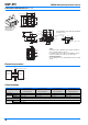
D6F-PH MEMS Differential pressure Sensor
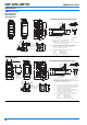
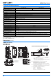
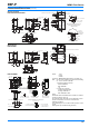
Connections/Dimensions (Unit: mm)
Electrical connection
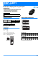
Communication
D6F-PH0025AD1
D6F-PH0505AD3
D6F-PH5050AD3
D6F-PH0025AD1-1
D6F-PH0505AD3-1
D6F-PH5050AD3-1
D6F-PH0025AD1-2
D6F-PH0505AD3-2
D6F-PH5050AD3-2
D6F-PH0025AD1-3
D6F-PH0505AD3-3
D6F-PH5050AD3-3
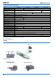
Serial Interface I2C
Master/Slave
HEX 0x6C 0x6D 0x6E 0x6F
BIN (7bit) 0b110_1100 0b110_1101 0b110_1110 0b110_1111
Speed mode Max. 400kHz (Fast Mode)
Signal
SCL Serial Clock
SDA Data Signal
Four, through hole 0.8 dia.
Three, 2
Two, 4 dia.
Two, R2
Two, through
hole 2 dia.
Two, through h
ole 2.2 dia
Recommendation size for pin header installation
(tolerrances: ±0.1)
Pin Header
1.2
3.1
2:GND
4:SCL
1:SDA
3:VCC
7.2
12
10.5
6.5
(2.6)
5
4
10.3
22
Four, 0.48 dia.
(3.7)
Two, 4.9 dia
Two, 4 dia.
3.35
16.5
Three, 2
5.25
Two, through hole 2 dia
26
20 10
16.5
18
7.05
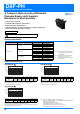
Low pressure side
High pressure side
Tubes
Install tubes made of materials such as rubber, urethane or
nylon so that they will not come out.
For urethane tubes, tubes with an outer diameter of 6 mm
and an inner diameter of 4 mm are recommended.
Soldering Conditions
Use a soldering iron for 5 s at 350°C with a pressure of 100
gf max.
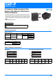
Mounting Direction
Install the Sensor so
that the joints are
facing upward.
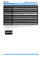
Sensor
(slave)
Master
SCL
pull-up resister 2.2 k
Ω
pull-up resister 2.2 k
Ω
Vcc 3.3 V
Vcc
Vcc
GND
SDA