
Datasheet


131
Text
130
Text
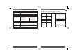
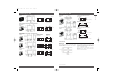
PCB Power Relay – G2R
SPDT Relays
G2R-1-T
Relays with Quick-connect Terminals
SPST-NO Relays
G2R-1A-T
Note: Model number of quick-connect terminal
is 187.
30.5 max.
7.5
5.2 5.2
17.4
Five, 1.3-dia. holes
4.75 0.5
8.5
29.5 max.
2.5
45 max.
14 max.
30.5 max.
7.5
17.4
5.2
Five, 1.3-dia. holes
4.75 0.5
8.5
29.5 max.
2.5
45 max.
14 max.
Mounting Holes (Bottom View)
Tolerance: ±0.1
38
Two M3 or two 3.5 dia.
Terminal Arrangement/Internal Connections
(Bottom View)
Mounting Holes (Bottom View)
Terminal Arrangement/Internal Connections
(Bottom View)
38
Two M3 or two 3.5 dia.
1
5
4 32
1
5
4 3
(No coil polarity)
(No coil polarity)
*Average value
(29.7)*
(13.1)*
(43.9)*
(43.9)*
(13.1)*
(29.7)*
*Average value
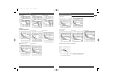
Precautions
■
Mounting
When mounting a number of relays on a PCB, be sure to provide
a minimum mounting space of 5 mm between the two juxtaposed
relays as shown below.
The above minimum mounting space is necessary due to mutual
thermal interference generated by the relays. This restriction may
be ignored, however, depending on the operating conditions of
the relays. Consult OMRON for details.
There is no restriction on the mounting direction of each relay on
the PCB.
When using this circuit, confirm the set and reset states and then
take into account the circuit constant.
5 mm min.
5 mm min.
CAT. No. K013-E2-12A-X
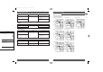
PCB Power Relay – G2R
DPST-NO Relays
G2R-2A4
Double-winding Latching Relays with PCB Terminals
SPDT Relays
G2RK-1
29 max.
13.5 max.
25.5 max.
4
0.3
0.15
0.5
1
29 max.
13 max.
25.5 max.
(25.2)*
4
(0.3)
0.3
1
0.5
1
20
5
7.5
(2.7)
(2.1)
(2.1)
Six, 1.3-dia.
holes
20
7.5
3.5 3.5
(2.1)
Seven, 1.3-dia.
holes
5
(2.7)
1
8
34
65
1
7
3
4
5
2
6
SR
+
-
+
-
*Average value
*Average value
(24.7)*
(28.8)*
(12.8)*
(12.8)*
(28.6)*
(No coil polarity)
(After confirming coil
polarity, wire correctly.)
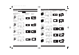
Double-winding Latching Relays with PCB Terminals
SPST-NO Relays
G2RK-1A
Mounting Holes
(Bottom View)
Terminal Arrangement/
Internal Connections
(Bottom View)
Tolerance: ±0.1
DPDT Relays
G2RK-2
DPST-NO Relays
G2RK-2A
29 max.
13 max.
25.5 max.
(25.2)*
(0.3)
4
0.3
0.5
1
0.16
1
29 max.
13 max.
25.5 max.
(25.2)*
(0.3)
4
0.3 0.18
0.18
1
1
0.15
29 max.
13 max.
25.5 max.
(0.3)
4
0.3
0.18
1
1 0.15
20
7.5
3.5
(2.1)
(2.7)
Six, 1.3-dia.
holes
5
10
5 5
7.5
(2.7)
(2.1)
(2.1)
Eight, 1.3-dia.
holes
5
(2.7)
5
7.5
(2.7)
(2.1)
(2.1)
Six, 1.3-dia.
holes
5
15
(2.7)
1
7
4
5
2
6
SR
+
-
+
-
1
10
45
3
7
68
2
9
SR
+
-
+
-
1
10
4
5
7
6
2
9
SR
+
-
+
-
(After confirming coil
polarity, wire correctly.)
(After confirming coil
polarity, wire correctly.)
(After confirming coil
polarity, wire correctly.)
(28.8)*
(12.8)*
(12.8)*
(28.8)*
*Average value
*Average value
Power Relays
Omron 08 Cat 1-302 5/10/07 15:39 Page 130