
Datasheet

4
G2RL PCB Power Relay
G
2
R
L
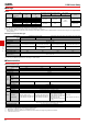
■Electrical Endurance Data (Reference Value)
Note. The results shown reflect values at ambient temperature 23°C. Electrical endurance will vary depending on the test conditions.
Contact your OMRON representative if you require more detailed information for the electrical endurance under your test condition.
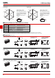
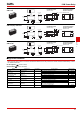
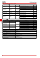
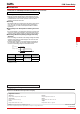
■Dimensions (Unit: mm)
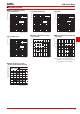
●Shock Malfunction
G2RL-1-E
8 A 250 VAC (cosφ=0.4)
8 A 30 VDC (L/R=7 ms)
200,000 operation min. (N.O.)
10,000 operation min. (N.O.)
G2RL-1
5 A 250 VAC (cosφ=0.4)
5 A 30 VDC (L/R=7 ms)
150,000 operation min. (N.O.)
10,000 operation min. (N.O.)
G2RL-2
8 A 250 VAC (cosφ=1)
8 A 30 VDC
30,000 operation min.
10,000 operation min.
G2RL-1A-E
Pilot duty (A300), 250 VAC
Pilot duty (A300), 125 VAC
250,000 operation min.
150,000 operation min.
Z
Z'
Shock direction
Y
Y'
XX'
Z'
Z
Y
Y'
X'
X
1,000
1,000
1,000
1,0001,000
1,000
NC contact
130
NO contact
Unit: m/s
2
Z
Z'
Shock direction
Y
Y'
XX'
Z'
Z
Y
Y'
X'
X
1,000
1,000
1,000
1,0001,000
1,000
NC contact
150
NO contact
Unit: m/s
2
1-pole type 2-pole type
Sample: G2RL-14 12 VDC
Number of Relays: 5 pcs
Test conditions: Shock is applied
in ±X, ±Y, and ±Z directions three
times each with without energizing
the Relays to check the number of
malfunctions.
Requirement: None malfuction
100 m/s
2
Sample: G2RL-24 12 VDC
Number of Relays: 5 pcs
Test conditions: Shock is applied
in ±X, ±Y, and ±Z directions three
times each with without energizing
the Relays to check the number of
malfunctions.
Requirement: None malfuction
100 m/s
2
1
4
3
5
(2.5)
15.7 max.
(15.5)*
3.5
0.5
0.50.5 0.8
29 max.
(28.8)*
12.7 max.
(12.5)*
Four, 1.3-dia. holes
3.5
7.5
(2.3) 20
* Average value
G2RL-1A, G2RL-1A4, G2RL-1A-H
PCB Mounting Holes
(Bottom View)
(No coil polarity)
Terminal Arrangement/
Internal Connections
(Bottom View)
15.7 max.
(15.5)*
3.5
0.5
0.5
0.5 0.8
0.5
29 max.
(28.8)*
12.7 max.
(12.5)*
3.5
Five, 1.3-dia. holes
(2.5) 1 2
4
3
5
3.5
7.5
(2.3) 20
* Average value
G2RL-1, G2RL-14, G2RL-1-H,
G2RL-1-HA
PCB Mounting Holes
(Bottom View)
(No coil polarity)
Terminal Arrangement/
Internal Connections
(Bottom View)
13
6
4
58
(2.5)
15.7 max.
(15.5)*
3.5
0.5
0.8
29 max.
(28.8)*
12.7 max.
(12.5)*
Six, 1.3-dia. holes
5
7.5
(2.3) 20
* Average value
0.50.5
G2RL-1A-E(-HA), G2RL-1A4-E,
G2RL-1A-E-CV(-HA), G2RL-1A-E-ASI
PCB Mounting Holes
(Bottom View)
(No coil polarity)
Terminal Arrangement/
Internal Connections
(Bottom View)