
Datasheet

4
G5NB PCB Power Relay
G
5
N
B
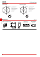
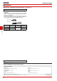
■Dimensions (Unit: mm)
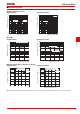
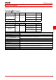
●Shock malfunction
Standard models High-capacity models
Z
Z
Z'
Z'
Shock direction
Unit: m/s
2
Y
Y
Y'
Y'
X
X
X'
X'
1,000
1,000
1,000
1,000
1,000 1,000
Energized
De-energized
700
125
Test Item: G5NB-1A, 24VDC
Number of Relays: 5 pcs
Test Method: Shock is applied 3
times in 6 directions along 3 axes
and the level at which shock caused
malfunction is measured.
The energized voltage is 100% of
the rated voltage.
Rating: 100 m/s
2
Z
Z
Z'
Z'
Shock direction
Unit: m/s
2
Y
Y
Y'
Y'
X
X
X'
X'
1,000
1,000
1,000
1,000
1,000 1,000
Energized
De-energized
700
125
Test Item: G5NB-1A-E, 24VDC
Number of Relays: 5 pcs
Test Method: Shock is applied 3
times in 6 directions along 3 axes
and the level at which shock caused
malfunction is measured.
The energized voltage is 100% of
the rated voltage.
Rating: 100 m/s
2
711.5
20.5max.
(20.4)*
15.3max.
(15.0)*
7.2max.
(7.0)*
4.7
(1.05)
(1.15)
Four, 1.1 dia.
21
4
3
3.4
@0.4
11.5 7
0.27 0.33
0.8
4.7
*Average value
G5NB-1A(4)(-E)(-HA)(-CF)(-PW)
PCB Mounting Holes
(Bottom View)
Tolerance: ±0.1 mm
(No coil polarity)
Terminal Arrangement/
Internal Connections
(Bottom View)