
Datasheet


2
G5RL-U/-K PCB Power Relay
G
5
R
L
-
U
/
-
K
●Contacts
■Characteristics
Note. Values in the above table are initial values.
*1. The contact resistance is measured with 1 A applied at 5 VDC using a fall-of-potential method.
*2. These are measured at a coil temperature of 23°C and rated coil voltage.
Pulse duty factor should be 10% MAX.
*3. The contact resistance is measured with 1 A applied at 5 VDC using a fall-of-potential method.
*4. Operated with input pulse width “30 ms”.
■Engineering Data
Load Resistive load
Contact form SPST-NO (1a) SPDT (1c)
Contact type Single
Contact material Ag Alloy (Cd free)
Rated load
16 A at 250 VAC
16 A at 24 VDC
16 A at 250 VAC (N.O)
5 A at 250 VAC (N.C)
16 A at 24 VDC (N.O)
5 A at 24 VDC (N.C)
Rated carry current 16 A 16 A (N.O), 5A (N.C)
Max. switching
voltage
250 VAC, 24 VDC
Max. switching
current
16 A 16 A (N.O), 5 A (N.C)
Classification SPST-NO (1a), SPDT (1c)
Item Relay function Single-winding Latching, Double-winding Latching
Contact resistance *1 100 mΩ max.
Set time 15 ms max.
Reset time 15 ms max.
Minimum pulse width *2 30 ms
Maximum pulse width *2 1 min
Insulation resistance *3 1,000 MΩ min. (at 500 VDC)
Dielectric strength
Between coil and
contacts
6,000 VAC, 50/60 Hz for 1 min
Between contacts of
the same polarity
1,000 VAC, 50/60 Hz for 1 min
Impulse withstand
voltage
Between coil and
contacts
10 kV (1.2 × 50 μs)
Vibration sesistanse
Destruction 10 to 55 to 10 Hz, 0.75 mm single amplitude (1.5 mm double amplitude)
Malfunction
10 to 45 to 10 Hz, 0.75 mm single amplitude (1.5 mm double amplitude) at Set status
10 to 32 to 10 Hz, 0.75 mm single amplitude (1.5 mm double amplitude) at Reset status (Except SPST-NO)
Shock resistance
Destruction
1,000 m/s
2
Malfunction
150 m/s
2
at Set status
50 m/s
2
at Reset status (Except SPST-NO)
Durability
Mechanical *4 5,000,000 operations min.
Electrical *4 50,000 operations min.
Ambient operating temperature -40° to 85°C (with no icing or condensation)
Ambient operating humidity 5% to 85%
Weight Approx. 10 g
●Maximum Switching Power ●Ambient Temperature vs.
Maximum Coil Voltage
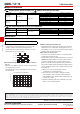
●Malfunction Shock
Note. Maximum voltage of Set pulse and Reset
pulse at duty factor 10%.
Sample: G5RL-K1A-E 12VDC
No. of relays: 5 pcs
Test Conditions:Shock is applied in ±X, ±Y, and ±Z
directions three times each with Set
and Reset status to check the number
of contact malfunctions.
Standard value:50 m/s
2
with Set status
100 m/s
2
with Reset status
Switching Current (A)
Switching voltage (V)
50
10
5
1
0.5
0.1
1 10 24 100 250 1000
AC resistive Load (N.C.)
DC resistive Load (N.C.)
16
140
120
100
80
60
40
20
0
130
−40 −20 0 20 40 60 80 85 100
Maximum voltage (%)
Ambient Temperature (˚C)
Z’
Z
Unit: m/s
2
Shock direction
Y
Y
Y’
Y’
X
X’
X’
X
NO
1,000
1,000
800
600
400
200
200
400
600
800
Z
Z’