
Datasheet


3
G5RL-U/-K PCB Power Relay
G
5
R
L
-
U
/
-
K
■Dimensions (Unit: mm)
20
5
29.0max.
(28.8)*
0.43
0.33
7.5
12.7max.
(12.5)*
1
@
0.5
3.5
15.7max.
(15.5)*
−U1A−E
(2.3)
7.5±0.1
Six, 1.3±0.1 dia.
20±0.1
5±0.1
–
R
+
+
S
–
134
568
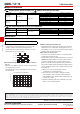
G5RL-U1A-E
* Average value
PCB Mounting Holes
(BOTTOM VIEW)
Terminal Arrangement/
Internal Connections
(BOTTOM VIEW)
Note. Check carefully the coil
polarity of the Relay.
Note. Orientation marks are indicated as follows:
20
5
5
29.0max.
(28.8)*
0.43
0.43
0.33
7.5
1
@
0.5
3.5
15.7max.
(15.5)*
12.7max.
(12.5)*
5±0.15±0.1
(2.3)
7.5±0.1
20±0.1
Eight, 1.3±0.1 dia.
34
56
2
7
–
R
+
+
S
–
1
8
G5RL-U1-E
−U1−E
* Average value
PCB Mounting Holes
(BOTTOM VIEW)
Terminal Arrangement/
Internal Connections
(BOTTOM VIEW)
Note. Orientation marks are indicated as follows:
Note. Check carefully the coil
polarity of the Relay.
G5RL-K1A-E
−K1A−E
20
5
29.0max.
(28.8)*
0.43
0.33
3.75 3.75
7.5
0.8
12.7max.
(12.5)*
1
@
0.5
3.5
15.7max.
(15.5)*
(2.3)
3.75±0.1
(3.75)
7.5±0.1
Seven, 1.3±0.1 dia.
20±0.1
5±0.1
34
56
–
R
+
S
–
1
8
9
* Average value
PCB Mounting Holes
(BOTTOM VIEW)
Terminal Arrangement/
Internal Connections
(BOTTOM VIEW)
Note. Orientation marks are indicated as follows:
Note. Check carefully the coil
polarity of the Relay.
G5RL-K1-E
−K1−E
20
5
5
29.0max.
(28.8)*
0.43
0.43
0.33
3.75 3.75
7.5
0.8
1
@
0.5
3.5
15.7max.
(15.5)*
12.7max.
(12.5)*
5±0.15±0.1
–
R
+
S
–
134
56
2
78
9
(2.3)
3.75±0.1
(3.75)
7.5±0.1
20±0.1
Nine, 1.3±0.1 dia.
* Average value
PCB Mounting Holes
(BOTTOM VIEW)
Terminal Arrangement/
Internal Connections
(BOTTOM VIEW)
Note. Orientation marks are indicated as follows:
Note. Check carefully the coil
polarity of the Relay.