
Brochure


19
Technical Information – Relays
Changes in Must Operate Voltage by Coil Temperature Rise
The coil resistance of a DC-switching relay increases (as the coil
temperature rises) when the coil has been continuously energized,
de-energized once, and then immediately energized again. This
increase in the coil resistance raises the voltage value at which the
relay operates. Additionally, the coil resistance rises when the
relay is used at a high ambient temperature.
Maximum Must Operate Voltage
The maximum voltage applicable to a relay is determined in
accordance with the coil temperature rise and the coil insulation
materials’ heat resistivity, electrical as well as mechanical life,
general characteristics, and other factors.
If a voltage exceeding the maximum voltage is applied to the
relay, it may cause the insulation materials to degrade, the coil to
be burnt, and the relay to not operate at normal levels. Actually,
however, there are occasions when the maximum voltage is
exceeded to compensate for fluctuation in the supply voltage. In
this event, pay attention to the following points.
The coil temperature must not exceed the temperature that the
spool and wound wire constituting the coil can withstand. The
following table shows the wires often used for a coil. In this table,
the coil temperature is measured through calculation of the coil
resistance.
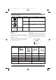
Wire material Maximum coil temperature
Polyurethane (UEW) 120˚C
Polyester (PEW) 130˚C
How to Calculate Coil Temperature
where,
R1 (Ω): coil resistance before energization
R2 (Ω): coil resistance after energization
T1 (˚C): coil temperature (ambient) before energization
t (˚C): coil temperature after energization
Before using the relay confirm that there are no problems.
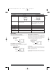
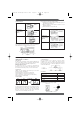
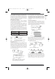
DC Input Power Source
Pay attention to the coil polarity of the DC-switching relay. Power
sources for DC-operated relays are usually a battery or a DC
power supply, either with a maximum ripple of 5%. If power is
supplied to the relay via a rectifier, the must operate and must
release voltages vary with the ripple percentage. Therefore, check
the voltages before actually using the relay. If the ripple
component is extremely large, beat may occur. If this happens, it
is recommended that a smoothing capacitor be inserted as
shown in the following diagram.
If the voltage applied to the DC-operated coil increases or
decreases slowly, each contact of a multi-pole contact relay may
not operate at the same time. It is also possible for this situation
to result in the must operate voltage varying each time the relay
operates. Either way, circuit sequencing will not be correct. In
critical applications, the use of a Schmitt circuit is recommended
to reshape the DC waveform to trigger all contacts of the relay at
the same time.
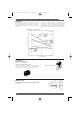
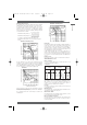
Relay Driving Signal Waveform
A long rise time and/or fall time of the signal driving the relay may
prolong the operate time and/or release time of the relay. This
situation may shorten the life of the contacts. If this situation
cannot be avoided, providing a Schmitt trigger circuit at the circuit
stage preceding the relay circuit will shape a waveform with sharp
transitions, as shown in the following diagram:
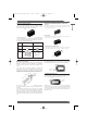
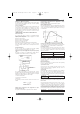
If the Schmitt trigger circuit is configured of transistors, a residual
voltage may exist in the output of the circuit. Therefore, confirm
that the rated voltage is present across the relay coil, or that the
residual voltage drops to zero when the relay releases. When an
IC (e.g., TC74HC132P) is used, this value is close to zero.
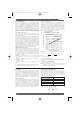
Cyclic Switching of AC Load
If the relay operates in synchronization with the supply voltage,
the life of the relay may be shortened. When designing the control
system in which the relay is used, estimate the life of the relay and
thus the reliability of the overall system under actual operating
conditions. Moreover, construct the circuit so that the relay
operates in a random phase or in the vicinity of the zero point.
t = (234.5+T1) + T1 [C°]
R2 - R1
R1
Smoothing capacitor
Ripple component
DC component
Relay
E min.
E max.
E mean
where,
E max.: maximum value of ripple component
E min.: minimum value of ripple component
E mean: mean value of DC component
Ripple percentage =
Emax. - Emin.
Emean
100
Waveform
shaping circuit
(Schmitt circuit with inverter)
Driver circuit
Vin
Vout
Contact
Vin
Vout
I
C
IB
TE
Vin
E
AC
Vin
E
AC
LOAD
PCB Relays
Omron A5 Catalogue 2007 1-282 11/9/06 10:16 am Page 19