
Brochure


12
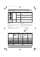
Technical Information – Relays
Contact ratings are generally indicated according to resistive
loads and inductive loads (cosϕ = 0.4 or L/R = 7 ms). Contact
shape and material are also shown to guide the customer in
selection of a model suitable for the intended load and required
service life.
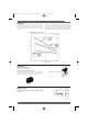
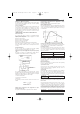
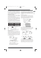
When used at extremely low loads, the failure rate differs
according to the contact material and contact method, as shown
in the figure. For example, in comparing a single contact point
with a bifurcated contact point, the bifurcated contact model has
higher parallel redundancy and will therefore exhibit a lower failure
rate.
■
Contacts
Failure Rate vs. Load Current
Failure rate (10 /operation)
−6
Gold-plated
single contract
Gold-plated
bifurcated
contact
Gold-clad
bifurcated
crossbar
contact
10 VDC (constant)
Load current (mA)
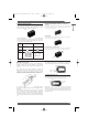
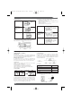
STRAIGHT PCB TERMINALS
PCB terminals are normally straight.
Self-clinching (S-shaped) PCB Terminals
Some relays have terminals that are bent into an “S” shape. This
secures the PCB relay to the PCB prior to soldering, helping the
terminals stay in their holes and keeping the relay level.
■
Terminals
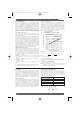
For miniature relays, the maximum dimensions and the average
values ( ) marked with an asterisk are provided to aid the customer
in designing.
■
Dimensions
Terminal
Quick-connect Terminals
16 max.
(15.9)*
8 max.
(7.9)*
0.3
3.5
0.6
0.4 x 0.4
9.9 max.
(9.8)*
7.62
0.25
*Average value
Omron A5 Catalogue 2007 1-282 11/9/06 10:16 am Page 12