
Brochure


13
Technical Information – Relays
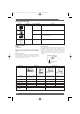
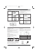
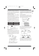
MOUNTING ORIENTATION MARK
On the top of all OMRON relays is a mark indicating where the
relay coil is located. Knowing the coil location aids in designing
PCBs when spacing components. Also, pin orientation is easy to
discern when automatic or hand-mounting relays.
On dimensional drawings in all OMRON literature this mark is left-
oriented. Mounting holes, terminal arrangements, and internal
connections follow this alignment. The following two symbols are
used to represent the orientation mark.
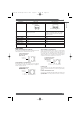
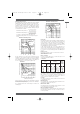
TERMINAL ARRANGEMENT/INTERNAL CONNECTIONS
Top View
If the terminal arrangement of a relay can be seen from above the
PCB, the top view of the relay is provided in the Dimensions section
of the catalog or data sheet.
Bottom View
If the relay’s terminals cannot be seen from above the PC board, as
in this example, a bottom view is shown.
Rotation Direction to Bottom View
The bottom view shown in the catalog or data sheet is rotated in the
direction indicated by the arrow, with the coil always on the left.
■ Moving Loop System
In the U.S.A., the National Association of Relay Manufactures
(NARM) in April 1984, awarded OMRON for monumental
advances in relay technology, as embodied in the Moving Loop
System.
This unique relay construction maximizes electrical and
permanent magnet energy. A high-efficiency magnet adds to the
magnetic flux of the relay coil, which also allows for tighter
packing of relay parts. Relays having such a coil are known as
“polarized relays.” Details of construction are shown below.
The moving loop design has similarities with polarized relays;
however, the following two features make for a large performance
distinction.
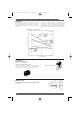
A permanent magnet is placed in the vicinity of the “working
gaps.” The flux energy of this permanent magnet complements
that of the electrical coil. This increased efficiency enables the
mechanism holding the contacts closed to ultimately switch larger
loads, and at the same time reduces the power consumed by the
coil.
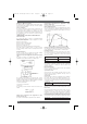
The following diagram shows concentric lines of magnetic flux
when the permanent magnet is placed near the working gap.
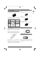
CONVENTIONAL RELAY COIL
The following diagram shows the lines of magnetic flux when the
permanent magnet is placed away from the working gap. These
lines of flux detract from the total strength of the coil.
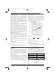
When the switching voltage is removed from the coil, the collapse
of the magnetic flux created by the permanent magnet and the
electrical coil provides the force to return the relay contacts to the
reset position. Note the flux path and magnet polarity in the
illustration overleaf.
Mark
Armature
Permanent
magnet
Air gap
Core
Movable
contact
Yo k e
Core
Permanent
magnet
Air gap
Permanent
magnet
Air gap
Axis of rotation
Drawing Bottom Top
view
Detail Mounting holes Terminal arrangement/
internal connections
Symbol
Example
Mark
(Bottom view)
Mark
(Bottom view)
PCB RelaysPCB Relays
Omron A5 Catalogue 2007 1-282 11/9/06 10:16 am Page 13