
Brochure


14
Technical Information – Relays
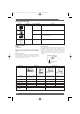
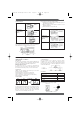
Release
Transition from
release to operation
(operating voltage
supplied)
Operation
Permanent
magnet
Repulsion
Movement
Attraction
Release
Transition from
release to operation
(operating voltage
supplied)
Operation
Released status is
maintained by per
manent magnet.
N
S
Repulsion
Attraction
The armature see
saws due to the at
traction and repul
sion torque exerted
on the armature by
the coil voltage and
the permanent
magnet.
N
S
N
S
Energized status
is maintained by
the coil voltage
and permanent
magnet.
N
S
N
S
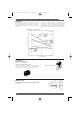
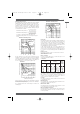
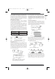
Super Moving Loop System
A very small high-sensitivity magnetic circuit is incorporated to
further minimize the conventional moving loop system.
This magnetic circuit has the following features:
1. High-efficiency polarized magnetic circuit utilizes power of
both attraction and repulsion.
2. Balanced armature system improves resistance to both
vibration and impacts.
3. Ideal mechanism for a low-profile relay.
Armature
Permanent
magnet
Core
Coil
Axis of
rotation
N
S
Note: The above applies to a latching relay.
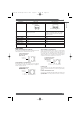
TERMS RELATED TO CONTACTS
Carry Current
The value of the current which can be continuously applied to the
relay contacts without opening or closing them, and which allows
the relay to stay within the permissible temperature rise.
Maximum Switching Current
A current which serves as a reference in determining the
performance of the relay contacts. This value will never exceed
the current flow. When using a relay, do not exceed this value.
Contact Form
OMRON uses the following relay terminology for the various
polarity and switch configurations.
SPST-NO (Single-pole, single-throw, normally open)
SPST-NC (Single-pole, single-throw, normally close)
SPDT (or changeover contact) (single-pole, double-throw)
DPDT (Double-pole, double–throw)
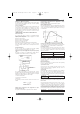
Contact Symbols
NO NC DT (NO/NC) MBB
Make-before-break (MBB) Contact
A contact arrangement in which part of the switching section is
shared between both an NO and NC contact. When the relay
operates or releases, the contact that closes the circuit operates
before the contact that opens the circuit releases. Thus both
contacts are closed momentarily at the same time.
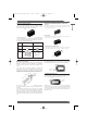
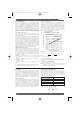
Contact Resistance
The total resistance of the conductor, as well as specific
resistivities such as of the armature and terminal, and the
resistance of the contacts. This value is determined by measuring
the voltage drop across the contacts by applying test currents as
shown in the table below.
Test Current
Rated current or switching current Test current (mA)
Less than 0.01 1
0.01 or higher but less than 0.1 10
0.1 or higher but less than 1 100
1 or higher 1,000
To measure the contact resistance, a milliohmmeter can also be
used, although the accuracy drops slightly.
■
Glossary
A: Ammeter
VVlt t
Contact sample
Power source
(DC or AC)
R
A: Ammeter
V: Voltmeter
R: Variable resistor
Milliohmmeter
Relay
COM
Probe
NC
Operating Principle
Omron A5 Catalogue 2007 1-282 11/9/06 10:16 am Page 14