
Brochure


15
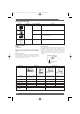
Technical Information – Relays
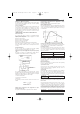
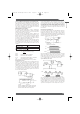
Maximum Switching Power
The maximum value of the load capacity which can be switched
without problem. When using a relay, do not exceed this value.
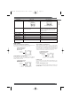
For example, when maximum switching voltage V
1
is known,
maximum switching current I
1
can be obtained at the point of
intersection on the characteristic curve “Maximum Switching
Power” shown below. Conversely, maximum switching voltage V
1
can be obtained if I
1
is known.
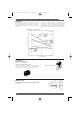
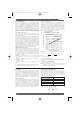
The life expectancy of the relay can be determined from the
“Endurance” curve shown below, based on the rated switching
current (I
1
) obtained above. For instance, the electrical endurance
at the obtained maximum switching current of 2 A is slightly over
300,000 operations (see circled point on graph below).
However, with a DC load, it may become difficult to break the
circuit of 48 V or more due to arcing. Determine the suitability of
the relay in actual usage testing.
The correlation between the contact ratings is shown in the
following figure:
Failure Rate
The failure rate indicates the lower limit of switching capability of
a relay as the reference value. Such minute load levels are found
in microelectronic circuits. This value may vary, depending on
operating frequency, operating conditions, expected reliability
level of the relay, etc. It is always recommended to double-check
relay suitability under actual load conditions.
In this catalog, the failure rate of each relay is indicated as a
reference value. It indicates failure level at a reliability level of 60%
(λ
60
).λ
60
=0.1x 10
-6
/operation means that one failure is presumed
to occur per 10,000,000 (ten million) operations at a reliability level
of 60%.
Number of Poles
The number of contact circuits. See Contact Form for reference.
TERMS RELATED TO COILS
Rated Coil Voltage
A reference voltage applied to the coil when the relay is used
under normal operating conditions.
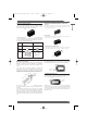
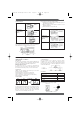
Coil Symbols
Coil Resistance (Applicable to DC-switching Relays only)
The resistance of the coil is measured at a temperature of 23˚C
with a tolerance of ±10% unless otherwise specified. (The coil
resistance of an AC-switching type relay may be given for
reference when the coil inductance is specified.)
Hot Start
The ratings set forth in the catalog or data sheet are measured at
a coil temperature of 23˚C.
Maximum Voltage
The maximum value of the pulsating voltage fluctuations in the
operating power supply to the relay coil.
Minimum Pulse Width
The minimum value of the pulsating voltage required to set and
reset a latching relay at a temperature of 23˚C.
Must Operate (Must Set) Voltage
The threshold value of a voltage at which a relay operates when
the input voltage applied to the relay coil in the reset state is
increased gradually.
Single-sided Double-winding
stable Latching
Polarised Non- w/4 w/3
polarised terminals terminals
Maximum switching current (I1) =
Maximum switching voltage (V
1) =
For instance, if the maximum switching voltage = 40 V
Maximum switching current = 2 A (see circled point on graph
below.)
Max. switching power [W(VA)]
Max. switching voltage (V1)
Max. switching power [W(VA)]
Max. switching current (I1)
Maximum Switching Power
Switching voltage (V)
Switching current (A)
AC resistive load
Max.
switching
voltage
DC resistive
load
Max. switching
power (DC)
Max. switching
power (AC)
DC (L/R = 7 ms)/AC
(cosf = 0.4) induc-
tive load
Max.
switching
current
Maximum Switching Power
Switching voltage (V)
Switching current (A)
AC resistive
load
AC induc-
tive load
(cosf = 0.4)
AC
resistive
load
DC induc-
tive load
(L/R = 7 ms)
Endurance
Switching current (A)
Endurance (x10 operations)
3
24-VDC
resistive load
24-VDC
inductive
load
110-VAC
inductive load
110-VAC
resistive load
Single-
winding
latching
+
−
+
−
+
−
SR
+
−
+
−
SR
+
− +
−
SR
PCB Relays
Omron A5 Catalogue 2007 1-282 11/9/06 10:16 am Page 15