
Brochure


16
Technical Information – Relays
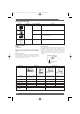
Must Release (Must Reset) Voltage
The threshold value of a voltage at which a relay releases when
the rated input voltage applied to the relay coil in the operating
state is decreased gradually.
Power Consumption
The power (= rated voltage x rated current) consumed by the coil
when the rated voltage is applied to it. A frequency of 60 Hz is
assumed if the relay is intended for AC operation. The current
flows through the coil when the rated voltage is applied to the coil
at a temperature of 23˚C. The tolerance is
+15%
/
-20%
unless
otherwise specified.
TERMS RELATED TO ELECTRICAL CHARACTERISTICS
Dielectric Strength
The critical value which a dielectric can withstand without
rupturing when a high-tension voltage is applied for 1 minute
between the following points:
Between coil and contact
Between contacts of different polarity
Between contacts of same polarity
Between set coil and reset coil
Between current-carrying metal parts and ground terminal
Note that normally a leakage current of 3 mA is detected;
however, a leakage current of 1 mA to 10 mA may be detected on
occasion.
Electrical Endurance
The life of a relay when it is switched at the rated operating
frequency with the rated load applied to its contacts.
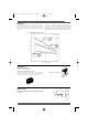
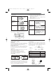
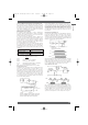
High-frequency Isolation (Applicable to High-frequency Relay
only)
The degree of isolation of a high-frequency signal, which is
equivalent to the insulation resistance of ordinary relays.
The following characteristics are measured with contacts
unrelated to the measurement terminated at 50Ω, when a signal is
applied from input terminal 11 to output terminal 8 or from input
terminal 11 to output terminal 14 of the sample.
1. Isolation characteristics
2. Insertion loss characteristics
3. Return loss
The following conversion formula converts from return loss to
VSWR.
High-frequency Switching Power (Applicable to High-
frequency Relays Only)
The power of a high-frequency signal that can be switched.
High–frequency Transmitted Power (Applicable to High-
frequency Relays Only)
The transmission capacity of a high-frequency signal.
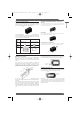
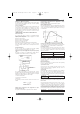
Impulse Withstand Voltage
The critical value which the relay can withstand when the voltage
surges momentarily due to lightning, switching an inductive load,
etc. The surge waveform which has a pulse width of ±1.2 x 50 µs
is shown below:
Insertion Loss (Applicable to High-frequency Relays Only)
The attenuation of a high-frequency signal in a transmission line
and is equivalent to the contact resistance of ordinary relays.
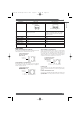
Insulation Resistance
The resistance between an electric circuit such as the contacts
and coil, and grounded, non-conductive metal parts such as the
core, or the resistance between the contacts. The measured
values are as follows:
Rated insulation voltage Measured value
60 V max. 250 V
61 V min. 500 V
Maximum Operating Frequency
The frequency or intervals at which the relay continuously
operates and releases, satisfying the rated mechanical and
electrical endurance.
Mechanical Endurance
The life of a relay when it is switched at the rated operating
frequency without the rated load.
Operate Bounce Time
The bounce time of the normally open (NO) contact of a relay
when the rated coil voltage is applied to the relay coil at an
ambient temperature of 23˚C.
Operate Time
The time that elapses after power is applied to a relay coil until the
NO contacts have closed, at an ambient temperature of 23˚C.
Bounce time is not included. For the relays having an operate time
of less than 10 ms, the mean (reference) value of its operate time
is specified as follows:
Operate time 5 ms max. (mean value: approx. 2.3 ms)
Release Bounce Time
The bounce time of the normally closed (NC) contact of a relay
when the coil is de-energized at an ambient temperature of 23˚C.
Release Time
The time that elapses between the moment a relay coil is de-
energized until the NC contacts have closed, at an ambient
temperature of 23˚C. (With a relay having SPST-NO or DPST-NO
contacts, this is the time that elapses until the NO contacts have
operated under the same condition.) Bounce time is not included.
For the relays having an operate time of less than 10 ms, the
mean (reference) value of its operate time is specified as follows:
Release time 5 ms max. (mean value: approx. 2.3 ms)
50-Ω termination
resistances
G5Y-154P
HP8505A
network
analyzer
HP8501A
storage
normalizer
HP8502A
transmission test set
OUT IN OUT
where,
x = return loss
1 − 10
VSWR =
−
1 + 10
20
x
−
20
x
Time (ms)
Surge voltage (%)
Peak value
Omron A5 Catalogue 2007 1-282 11/9/06 10:16 am Page 16