
Brochure


18
Technical Information – Relays
2) DC-switching Relays
This type of relay is often used as a so-called “marginal” relay that
turns ON or OFF when the voltage or current reaches a critical
value, as a substitute for a meter. However, if the relay is used in
this way, its control output may fail to satisfy the ratings because
the current applied to the coil gradually increases or decreases,
slowing down the speed at which the contacts move. The coil
resistance of the DC-switching relay changes by about 0.4% per
degree C change in the ambient temperature. It also changes
when the relay generates heat. This means that the must operate
and must release voltages may increase as the temperature rises.
Coil switching voltage Source
If the supply voltage fluctuates, the relay will be caused to
malfunction regardless of whether the fluctuation lasts for a long
time or only for a moment.
For example, assume that a large-capacity solenoid, relay, motor,
or heater is connected to the same power source as the relay, or
that many relays are used at the same time. If the capacity of the
power source is insufficient to operate these devices at the same
time, the relay may not operate, because the supply voltage has
dropped. Conversely, if a high voltage is applied to the relay (even
after taking voltage drop into account), chances are that the full
voltage will be applied. As a consequence, the relay’s coil will
generate heat. Therefore, be sure 1) to use a power source with
sufficient capacity and 2) that the supply voltage to the relay is
within the rated must operate voltage range of the relay.
Minimum Must Operate Voltage
When the relay is used at a high temperature, or when the relay
coil is continuously energized, the coil temperature rises and coil
resistance increases. Consequently, the must operate voltage
increases. This increase in the must operate voltage requires
attention when determining the minimum must operate voltage
are given below for reference when designing a power source
appropriate for the relay.
Assuming a coil temperature rise of 10˚C, the coil resistance will
increase about 4%. The must operate voltage increases as
follows:
Rated values of Model LZN2 taken from catalog or data sheet
Rated voltage: 12 VDC
Coil resistance: 500Ω
Must operate voltage: 80% max. of rated voltage at 23˚C coil
temperature
The rated current that flows through this relay can be obtained by
dividing the rated voltage by the coil resistance. Hence,
12 VDC ÷ 500Ω = 24 mA
However, the relay operates at 80% maximum of this rated
current, i.e., 19.2 mA (= 24 mA x 0.8). Assuming that the coil
temperature rises by 10˚C, the coil resistance increases 4% to
520Ω (= 500Ω x 1.04). The voltage that must be applied to the
relay to flow a switching current of 19.2 mA x 520Ω = 9.98 V. This
voltage, which is at a coil temperature of 33˚C (= 23˚C + 10˚C), is
83.2% of the rated voltage (= 9.98 V ÷ 12 V). As is evident from
this, the must operate voltage increases when the coil
temperature rises, in this example, 10˚C from 23˚C.
The minimum must operate voltage can be determined by this
expression.
where,
E (V): Rated coil voltage
Epv (%): Must operate voltage
Ta: Coil temperature for determining Epv (20˚C, unless otherwise
specified)
T (˚C): Ambient operating temperature
E
T
(V): Minimum must operate voltage
Note: In the above expression, T is taken to be the result of
energization of the coil, when the coil temperature is the
same as the ambient temperature.
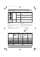
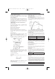
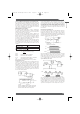
Coil Temperature vs.
Must Operate/release Voltage (LZN)
Ambient temperature (°C)
Percentage against rated value (%)
Must operate voltage
Must release voltage
Coil voltage: 24 VDC
N = 10 (mean value)
E
T
> E x x ( + 1) [V]
Epv + 5
100
T - Ta
234.5 + Ta
■ Coil Input
To guarantee accurate and stable relay operation, the first and
foremost condition to be satisfied is the application of the rated
voltage to the relay. Additionally, the rated voltage in light of the
type of the power source, voltage fluctuation, and changes in coil
resistance due to temperature rise. If a voltage higher than the
rated maximum voltage is applied to the coil for a long time, layer
short-circuiting and damage to the coil by burning may take
place.
Coil Temperature Rise
When a current flows through the coil, the coil’s temperature rises
to a measurable level, because of copper loss. If an alternating
current flows, the temperature rises even more, due not only to
the copper loss, but additionally to the iron loss of the magnetic
materials, such as the core. Moreover, when a current is applied
to the contact, heat is generated on the contacts, raising the coil
temperature even higher (however, with relays whose switching
current is rated at 2 A or lower, this rise is insignificant).
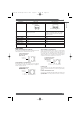
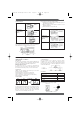
Temperature Rise by Pulsating Voltage
When a pulsating voltage having an ON time of less than 2
minutes is applied to the relay, the coil temperature rise varies,
and is independent of the duration of the ON time, depending only
on the ratio of the ON time to the OFF time. The coil temperature
in this case does not rise as high as when a voltage is
continuously applied to the relay.
Energization time Release temperature rise
Continuous energization 100%
ON:OFF = 3:1 approx. 80%
ON:OFF = 1:1 approx. 50%
ON:OFF = 1:3 approx. 35%
(V)
1:1
(t)
Omron A5 Catalogue 2007 1-282 11/9/06 10:16 am Page 18