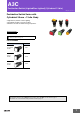
A3C Pushbutton Switch (Lighted/Non-Lighted) (Cylindrical 12-dia.) CSM_A3C_DS_E_2_1 Pushbutton Switch Series with Cylindrical 20-mm × 12-dia. Body • High-intensity uniform surface lighting. • Round body enables easy hole making. • Miniature size with excellent feeling of operation. RoHS Compliant Refer to Safety Precautions for All Pushbutton Switches and Safety Precautions on page 12.
A3C Model Number Legend .............................................When placing your order, specify the individual component part model numbers of the Pushbutton, Lamp (lighted models only), and Switch, as listed in the ordering tables below. For information on combinations, refer to Ordering Information on page 3.
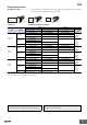
A3C Ordering Information Ordering as a Set ................................ The model numbers used to order sets of Units are given in the following tables. One set comprises the Pushbutton, Lamp (lighted models only), and Switch.
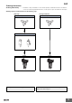
A3C Ordering Information Illumination-only and Colored-illumination LED Models "Illumination only" describes LED models for which the screen color is the same whether the LED is lit or not. Example: Red LED Not lit Cap (red) Red Legend plate (milky white) Lit Red Pushbutton Reflective plunger LED lamp (red) - - - Lamp "Colored illumination" describes LED models for which the screen color is white when the LED is not lit and changes to the color of the LED lamp when the LED is lit.
A3C Ordering Information Ordering Individually ............... Pushbuttons, Lamps, and Switches can be ordered separately. Combinations that are not available as sets can be created using individual Units. Also, store the parts as spares for maintenance and repairs. Ordering: Specify a model number from the following page. LED Lamp Non-lighted Models Operation Unit Operation Unit Lamps LED Lamp Incandescent Lamp Switch Ordering set combinations: Refer to page 3.
A3C Ordering Information Ordering Individually ................Pushbuttons, Lamps, and Switches can be ordered separately. Combinations that are not available as sets can be created using individual Units. Also, store the parts as spares for maintenance and repairs.
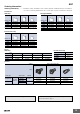
A3C Ordering Information Accessories, Replacements, and Tools Accessories Name Appearance Socket Insulation Cover Classification Model Wire-wrap terminal A3C-4101 PCB terminal A3C-4102 Solder terminal A3C-4103 --- A3C-3002 For rectangular models A3CJ-5050 For square, round models A3CA-5050 For rectangular models A3CJ-5060 Switch Guard Remarks Cannot be used with Insulation Cover. Cannot be used with Socket. Cannot be used with Dust Cover.
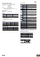
A3C Approved Standard Ratings Characteristics UL (File No. E41515), CSA (File No. LR45258) Standard Load: 0.5 A at 250 VAC 1 A at 125 VAC 1 A at 30 VDC 0.1 A at 125 VAC 0.1 A at 30 VDC Microload: Note: Certification has been obtained for the Switch Unit. For detailed information on individual products that have received certification, consult your supplier. Operating frequency Mechanical Momentary-action models: 120 operations/minute max. Alternate-action models: 60 operations/minute max.
A3C Nomenclature Model Structure Display Unit Structure Color cap (1) Shape of Pushbutton (2) Color of Pushbutton Legend Plate Pushbutton Reflective plunger Lamp (3) Type of Lamp Switch (4) Switch Specifications Note: (1) (2) The A3CJ model is shown here as a representative example.
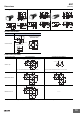
A3C Dimensions (Unit: mm) Rectangular Models/A3CJ Square Models/A3CA 9.5 6 20 Round Models/A3CT 6 1 9.5 20 9.5 20 9.5 9.5 6 0.6 9.5 0.6 0.6 M12 × 1 M12 × 1 M12 × 1 14 14 11.8 14 dia. 11.8 dia. 11.8 11.8 15.7 26.5 26.5 26.5 14 18 Terminal Connections Terminal SPST-NO + SPST-NC Lighted and non-lighted models Terminal Arrangement (BOTTOM VIEW) 0.6 6.5 t0.4 1.6 Solder terminal Lamp terminal t0.3 Terminal hole L+ NC NO L- NC NO 2 0.8 0.
A3C Dimensions (Unit: mm) Accessory Mounting Dimensions Dimensions with Socket Mounted (The diagrams below show the external dimensions for rectangular models as representative models.) Wire-wrap Terminal/A3C-4101 33.6 PCB Terminal/A3C-4102 33.6 15.8 16.7 Solder Terminal/A3C-4103 1 3.5 33.6 16.7 5 16.7 1 0.6 1.6 3.55 13.9 dia. 3.55 3.2 1.6 13.9 dia. 13.9 dia. 3.2 0.3 1 0.3 3.55 4.7 7 PCB Cutout (BOTTOM VIEW) 9.7±0.1 7 Terminal Hole Dimensions Six, 0.8 dia. 2 0.5 5.1± 0.1 7.4± 0.
A3C Safety Precautions Refer to Safety Precautions for All Pushbutton Switches. CAUTION Do not apply a voltage higher than the maximum rated operating voltage between the lamp terminals, as there is a risk that the incandescent lamp or LED lamp will be damaged, and the Pushbutton will be ejected.
A3C Application Mounting and Replacing the Pushbutton Panel Mounting (1) Mounting Direction for the Pushbutton/Display and Lamp Lighted Pushbutton Switch • Insert the Lamp (incandescent lamp or LED lamp) into the Pushbutton so that the lamp guide fits into the wider gap between the projections on the Pushbutton. Projections LED/lamp guide LED/lamp guide • Insert the Switch from the front of the panel. Mount the mounting nut from the terminal end of the Switch and tighten it.
A3C Mounting the Dust Cover 1. The Dust Cover separates into 2 parts: the cap and the mounting frame. 2. Insert the Switch into the mounting frame. (Align the lock projection with the recess on the mounting frame.) 3. Insert the Switch in the state described in step 2 into the panel. (Align the lock protrusion on the mounting frame with the hole in the panel.) 4. Mount the mounting nut from the back of the panel and tighten it. 5. Insert the cap into the mounting frame.