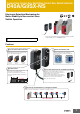
Compact Non-Contact Door Switch/Non-Contact Door Switch Controller D40A/G9SX-NS Electronic Detection Mechanism for Better Stability in Non-contact Door Switch Operation For the most recent information on models that have been certified for safety standards, refer to your OMRON website. Be sure to read the “Safety Precautions” on page 32. Features ● Easy-to-see 2-Color Indicators ● Mount from Either Side Switch status is easy to see at a glance with these red/yellow LED indicators.
D40A/G9SX-NS Solves Conventional Switch Issues to Provide Stable Detection Issue 1 The Switch does not accurately detect the door when it is closed slowly, resulting in an error. Conventional switch An error can occur if the door is closed slowly with conventional switches. Door closed slowly. Solution 1 Conventional Switches The D40A does not use reed switches and provides stable detection with electronic switches.
D40A/G9SX-NS Two Types of Controller to Solve Productivity, Expandability, and Maintenance Issues The G9SX-NS and G9SX-NSA are designed specifically for use with Non-contact door switch, and with the G9SX-NSA you can also connect mechanical safety door switches. Among other features, these Controllers support logical AND connections that enable partial stops. These Controllers make the most of D40A Switches.
D40A/G9SX-NS Reduce Costs with these New-Concept Controllers Issue 1 Two Controllers are required for emergency stop switches and non-contact door switches. Application ●One hazard. ●The system must be stopped when either a door is opened or an emergency stop switch is pressed. D40B Emergency stop switch * D40A Solution 1 D40B-J1 Emergency stop switch * The D40A Simplifies the Configuration The G9SA must be added to connect the G9SA emergency stop switch.
D40A/G9SX-NS Selection of Safety Controllers for D40A [Connectable Controllers] Safety Controller G9SP Non-contact Door Switch Controller G9SX-NS@ Safety Controller G9SP Non-contact Door Switch Controller G9SX-NS@ • Flexible programming by combining function blocks • Extensive system configurations • Decreased work hours by convenient configurator • Easy expansion of output points by an expansion unit • Improved maintainability by LED display • No special programming required Function Blocks * G9SP S
Compact Non-Contact Door Switch D40A Electronic Detection Mechanism for Better Stability • Up to 30 units can be connected to a G9SX-NS@ or G9SP. (The G9SP supports 2 channels and up to 15 units per channel.) • Compact Non-contact Door Switch can be mounted from both sides. • The cable length can be selected, reducing wiring restrictions, and Switches can be integrated into a single Switch with a connector, reducing inventory.
D40A Ordering Information List of Models Non-Contact Door Switches (Switch/Actuator) Classification Appearance Auxiliary outputs Cable length Model 2m D40A-1C2 5m D40A-1C5 Standard models Semiconductor outputs *1 Connector model 0.15 m D40A-1C015-F *2 Note: The Switch must be used in combination with a Non-Contact Door Switch Controller (G9SX-NS@) or Safety Controller (G9SP). *1. PNP open-collector semiconductor output. *2. The model with a connector is not KOSHA certified.
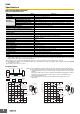
D40A Specifications Non-contact Door Switches Ratings and Characteristics Item Interlock type Coding level Model Operating distance OFF→ON Operating distance ON→OFF Operating Differential travel characteristics *2 Influence of temperature (max.
D40A Cable with connector Ratings and Characteristics Rated current 4A Rated voltage 250 VAC/VDC Contact resistance (Connector) 40 mΩ max. (20 mV max., 100 mA max.) Insulation resistance 1,000 MΩ min. (at 500 VDC) Dielectric strength (Connector) 1,500 VAC for 1 min (leakage current: 1 mA max.). Degree of protection IP67 (IEC60529) Insertion tolerance 200 times min.
D40A Connections Internal Circuit Diagram D40A-1C@ Brown Internal circuit Blue White Black Yellow D40A and G9SX-NS@ Wiring Example: Wiring a Single Switch Example: Wiring Multiple Switches Connect Up to 30 Non-contact Door Switches Blue Brown Black White Blue Brown Black White Blue Brown A2 Black D1 D2 D3 D4 Auxiliary output load *1 White Blue *2 Yellow Black Brown White D40A-1C@ G9SX-NS202-@ G9SX-NSA222-T03-@ *1. The auxiliary output load current must be 10 mA max. *2.
D40A Dimensions and Terminal Arrangement (Unit: mm) Non-contact Door Switch (Switch/Actuator) D40A-1C2 D40A-1C5 D40A-1C015-F Indicator (1.5) 2-4.2 dia. 9.5 7.2 dia. 38 7.2 dia. 48 48 7.2 dia. 12 7.2 dia. Sensing surface (150) 6 13 17 38 (2) 2-4.2 dia. 20 25 Vinyl-insulated round cable: Diameter 4 mm, 5-wire (Conductor cross-sectional area: 0.2 mm2/ Insulator diameter: 1.0 mm) Standard length: 2 m/5 m (46) (15 dia.
Non-Contact Door Switch Controller G9SX-NS Dedicated controller for Non-Contact Door Switch with programless and safety circuit configuration • Up to 30 units of D40A/D40Z Compact Non-Contact Door Switch can be connected to a single Controller. • Logical AND connection function provides easy system configuration for partial stop and complete stop. • Programless. • G9SX-NSA provides simultaneous inputs of a Non-Contact Door Switch and a conventional key-insertion type Safety Door Switch.
G9SX-NS Ordering Information List of Models Non-Contact Door Switch Controllers Safety outputs *1 Instantaneous 2 (Semiconductors) *1. *2. *3. *4. Logical AND connection input Auxiliary outputs *3 OFF-delayed *2 0 2 (Semiconductors) 2 (Semiconductors) Logical AND connection output Max. OFF delay time *4 Rated voltage --1 1 24 VDC 3.
G9SX-NS Specifications Non-contact Door Switch Controllers Ratings Power input Item Model G9SX-NS202-@ G9SX-NSA222-T03-@ Rated supply voltage 24 V DC Operating voltage range −15% to 10% of rated supply voltage Rated power consumption * 3 W max. 4 W max. G9SX-EX-@ 2 W max. * Power consumption of loads not included. Inputs Item Model Safety input *1 G9SX-NS202-@/G9SX-NSA222-T03-@ Operating voltage: 20.4 VDC to 26.4 VDC, internal impedance: approx. 2.8 kΩ *2 Feedback/reset input *1.
G9SX-NS Characteristics Item Model Over-voltage category (IEC/EN 60664-1) G9SX-NS202-@ G9SX-NSA222-T03-@ G9SX-EX-@ II (Relay outputs 13 to 43 and 14 to 44: III) II Logical AND connection input: 100 ms max. Operating time (OFF to ON state) *1 D40A connected: 100 ms max. D40Z connected: 200 ms max. Safety input: 50 ms max. *2 Logical AND connection input: 100 ms max. *3 D40A connected: 100 ms max. *3 D40Z connected: 200 ms max. *3 30 ms max. *4 15 ms max.
G9SX-NS Logical AND Connection Item Model G9SX-NS202-@ G9SX-NSA222-T03-@ G9SX-EX-@ Number of Units connected per logical 4 Units max. AND output --- Total number of Units connected by logical AND *1 20 Units max. --- Number of Units connected in series by logical AND 5 Units max. --- Max. number of Expansion Units connected *2 Maximum cable length for logical AND input --- 5 Units max. 100 m max. --- Note: See Logical AND Connection Combinations below for details. *1.
G9SX-NS Response Time and Operating Time 1. G9SX-NS@ Logical AND input Max. response time Max. operating time (excluding Expansion Units) *1 (excluding Expansion Units) *2 Non-contact Door Switch input Non-contact Door Switch input D40A connected: 20 ms max. *3 D40Z connected: 45 ms max. *3 D40A connected: 100 ms max. *4 D40Z connected: 200 ms max. *4 Logical AND input 15 ms 100 ms *1.
G9SX-NS Connections Internal Connection G9SX-NS202-@ (Non-contact Door Switch Controller) A1 D1 D2 D3 D4 T31 T32 T33 T41 T42 Non-contact Door Reset/Feedback Input Switch control *2 Logical AND input G9SX-NSA222-T03-@ (Non-contact Door Switch Controller) A1 Power supply circuit *1 A2 Safety output control S14 S24 *2 Power supply circuit *1 Auxiliary output control L1 X1 A2 G9SX-EX401-@/G9SX-EX041-T-@ (Expansion Unit/Expansion Unit OFF-delayed Model) 13 23 33 43 *1 Exp. sig.
G9SX-NS D40A, D40Z and G9SX-NS@ Wiring Example: Wiring a Single Switch D40A D40Z Blue Black White Yellow D1 D2 D3 D4 Auxiliary output load *1 Brown D40Z-1C@ *2 Blue Black Brown White D40A-1C@ D1 D2 D3 D4 A2 G9SX-NS202 G9SX-NSA222 G9SX-NS202-@ G9SX-NSA222-T03-@ *1. The auxiliary output load current must be 10 mA max. *2. When connecting a XS2F series connector with cable to a connector type, the color of the auxiliary output cable is gray.
G9SX-NS Wiring of Inputs and Outputs G9SX-NS202-@ Signal name Power supply input Terminal name A1, A2 Non-contact D1, D2, Door Switch input D3, D4 Description of operation Connect the power source to the A1 and A2 terminals. Wiring Connect the power supply plus (24 VDC) to the A1 terminal. Connect the power supply minus (GND) to the A2 terminal. All Non-contact Door Switch inputs connected to the G9SX-NS@ must be ON as a required condition for the safety outputs to be ON.
G9SX-NS G9SX-NSA222-T03-@ Signal name Power supply input Terminal name A1, A2 Description of operation Connect the power source to the A1 and A2 terminals. Wiring Connect the power supply plus (24 VDC) to the A1 terminal. Connect the power supply minus (GND) to the A2 terminal. +24 V Using safety input 1 system Safety input 1 T11 T12 T21 T22 To set the safety outputs in the ON state, the high state signals must be input to both safety input 1 and safety input 2.
G9SX-NS Dimensions and Terminal Arrangement (Unit: mm) Non-contact Door Switch Controller (6) (See note 2.) G9SX-NS202-@ Terminal arrangement T31 T32 T33 D3 D1 D2 X1 A1 T31 T32 T33 D3 D1 D2 X1 A1 G9SX-NS202 24VDC PWR FB AND NS EI 100 max. PWR FB AND NS ERR EI ERR No. T41 T42 X2 S14 S24 L1 A2 D4 T41 T42 X2 A2 S14 S24 L1 D4 23 max. 115 max. (22.5) * (6) (See note 2.) Note: 1. Above outline drawing is for models with spring-cage terminals (-RC). 2.
G9SX-NS Operation Functions Logical AND Connection Connecting Expansion Units A logical AND connection means that the G9SX outputs a safety signal “a” to another G9SX, and that G9SX creates the logical AND of safety signal “a” and safety signal “b.” The safety output of the G9SX-NSA222-T03-@ with the logical AND connection shown in the following diagram is “a” AND “b.
G9SX-NS Setting Procedure 1. Cross Fault Detection (G9SX-NSA222-T03-@) Set the cross fault detection mode for safety inputs by shorting Y1 to 24 V or leaving it open. When cross fault detection is set to ON, short-circuit failures are detected between safety inputs T11-T12 and T21-22. When a cross fault is detected, the following will occur. (1) The safety outputs and logical AND outputs lock out. (2) The LED error indicator is lit. (3) The error output (auxiliary output) turns ON. 3.
G9SX-NS LED Indicators G9SX-NS202 G9SXNSA222 G9SX-EX G9SX-EX-T Power supply indicator ❍ ❍ ❍ ❍ Lights while power is supplied. Orange Safety input #1 indicator --- ❍ --- --- Lights while a high signal is input to T12. Flashes when an error relating to safety input #1 occurs. T2 Orange Safety input #2 indicator --- ❍ --- --- Lights while a high signal is input to T22. Flashes when an error relating to safety input #2 occurs.
G9SX-NS Fault Detection When the Non-contact Door Switch Controller detects a fault, the ERR indicator and/or other indicators light up or flash to inform the user about the fault. Check and take necessary measures referring to the following table, and then re-supply power to the Non-contact Door Switch Controller. (G9SX-NS202-@/NSA222-T03-@) ERR indicator Other indicator --- Flashes T1 flashes T2 flashes NS flashes Fault Lights 1. Excessive electromagnetic disturbance 2.
G9SX-NS ERR indicator Other indicator Fault Expected causes of the fault 1. Error in the wiring of the logical AND connection input AND flashes Fault involved with logical AND connection input 2. Incorrect setting for the logical AND connection input 3. Failure of the circuit of the logical AND connection input Lights Supply voltage outside the 1. Supply voltage outside the rated All indicators rated value value except PWR flash Check points and measures to take 1. Check the wiring to T41 and T42.
G9SX-NS Application Examples Example 1: Connection with D40A Highest achievable PL/safety category PLd/3 equivalent Model Stop category Reset 0 Manual Emergency Stop Switch A165E/A22E Non-contact Door Switch D40A Non-contact Door Switch Controller G9SX-NSA222-T03-@ Note: The PL evaluation result on this connection example applies to safety functions related to the D40A Non-Contact Door Switch. The above PL is only the evaluation result of the example.
G9SX-NS Example 2: Connection with D40A Highest achievable PL/safety category Model Stop category Emergency Stop Switch A165E/A22E Non-contact Door Switch D40A Flexible Safety Unit G9SX-BC202-@ Non-contact Door Switch Controller G9SX-NS202-@ PLd/3 equivalent Reset Emergency Stop Switch: Manual Non-contact Door Switch: Auto 0 Note: The PL evaluation result on this connection example applies to safety functions related to the D40A Non-Contact Door Switch.
G9SX-NS Example 1: Connection with D40Z Highest achievable PL/safety category PLe/4 equivalent Model Stop category Reset 0 Manual Emergency Stop Switch A165E/A22E Non-contact Door Switch D40Z Non-contact Door Switch Controller G9SX-NSA222-T03-@ Note: The above PL is only the evaluation result of the example. The PL must be evaluated in an actual application by the customer after confirming the usage conditions.
G9SX-NS Example 2: Connection with D40Z Highest achievable PL/safety category Model Stop category Emergency Stop Switch A165E/A22E Non-contact Door Switch D40Z Flexible Safety Unit G9SX-BC202-@ Non-contact Door Switch Controller G9SX-NS202-@ PLe/4 equivalent Reset Emergency Stop Switch: Manual Non-contact Door Switch: Auto 0 Note: The above PL is only the evaluation result of the example. The PL must be evaluated in an actual application by the customer after confirming the usage conditions.
D40A/G9SX-NS Safety Precautions Be sure to read the Common Precautions for Safety Warning at the following URL: http://www.ia.omron.com/. Indication and Meaning for Safe Use WARNING Indicates a potentially hazardous situation which, if not avoided, will result in minor or moderate injury, or may result in serious injury or death. Additionally there may be significant property damage. Precautions for Safe Use Supplementary comments on what to do or avoid doing, to use the product safely.
D40A/G9SX-NS 18. Connect to the G9SX-NS@ only appropriate components or devices complying with relevant safety standards corresponding to the required level of safety category. Conformity to requirements of safety category must be determined as an entire system. It is recommended to consult an authorized certification body regarding assessment of conformity to the required safety level. 19. OMRON is not responsible for conformity with any safety standards covering the customer's entire system. 20.
D40A/G9SX-NS 12. When two or more Switches are mounted side-by-side, they must be no closer than 25 mm in the X, Y, and Z directions. 25 mm min. 25 mm min. 25 mm min. 13. Check that the machine is stopped whenever the interlocked guard door is open. 19.
D40A/G9SX-NS 24. Set the time duration of OFF-delay to an appropriate value that does not cause the loss of safety functions of system. 25. Logical AND connections between Units (Refer to “Functions” on page 23.) 1. To use logical AND connection inputs, enable the logical AND connection input for the G9SX-NS@ that will receive the inputs. 2. Connect the logical AND connection inputs appropriately to the logical AND connection outputs of the G9SX-@. 3.
Terms and Conditions Agreement Read and understand this catalog. Please read and understand this catalog before purchasing the products. Please consult your OMRON representative if you have any questions or comments. Warranties. (a) Exclusive Warranty. Omron’s exclusive warranty is that the Products will be free from defects in materials and workmanship for a period of twelve months from the date of sale by Omron (or such other period expressed in writing by Omron).
OMRON Corporation Industrial Automation Company Authorized Distributor: Kyoto, JAPAN Contact: www.ia.omron.com Regional Headquarters OMRON EUROPE B.V. Wegalaan 67-69, 2132 JD Hoofddorp The Netherlands Tel: (31)2356-81-300/Fax: (31)2356-81-388 OMRON ELECTRONICS LLC 2895 Greenspoint Parkway, Suite 200 Hoffman Estates, IL 60169 U.S.A. Tel: (1) 847-843-7900/Fax: (1) 847-843-7787 OMRON ASIA PACIFIC PTE. LTD. No.