Compact Non-Contact Door Switch/Flexible Safety Unit D40A/G9SX-NS CSM_D40A_G9SX-NS_DS_E_3_2 Electronic Detection Mechanism for Better Stability in Non-contact Door Switch Operation Be sure to read the “Safety Precautions” on page 24 and the “Precautions for All Safety Door Switches”. Features ● Easy-to-see 2-Color Indicators ● Mount from Either Side Switch status is easy to see at a glance with these red/yellow LED indicators. Red: Open door detected. Yellow: Closed door detected.
D40A/G9SX-NS Solves Conventional Switch Issues to Provide Stable Detection Issue 1 The Switch does not accurately detect the door when it is closed slowly, resulting in an error. Conventional switch An error can occur if the door is closed slowly with conventional switches. Door closed slowly. Solution 1 Conventional Switches The D40A does not use reed switches and provides stable detection with electronic switches.
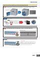
D40A/G9SX-NS Two Types of Controller to Solve Productivity, Expandability, and Maintenance Issues The G9SX-NS and G9SX-NSA are designed specifically for use with the D40A, and with the G9SX-NSA you can also connect mechanical safety door switches. Among other features, these Controllers support logical AND connections that enable partial stops. These Controllers make the most of D40A Switches.
D40A/G9SX-NS Reduce Costs with these New-Concept Controllers Issue 1 Two Controllers are required for emergency stop switches and non-contact door switches. Application ●One hazard. ●The system must be stopped when either a door is opened or an emergency stop switch is pressed. D40B Emergency stop switch * D40A Solution 1 D40B-J1 Emergency stop switch * The D40A Simplifies the Configuration The G9SA must be added to connect the G9SA emergency stop switch.
D40A/G9SX-NS Model Number Structure Model Number Legend Non-Contact Door Switch (Switch/Actuator) D40A - @@@ 1 2 3 1. Type 1: Standard model 2. Auxiliary outputs C: 1NO (PNP transistor output) 3. Cable length 2: 2 m 5: 5 m Non-Contact Door Switch Controller G9SX - @@@@@@ - @@@ - @@ 1 2 3 4 5 1. Functions NS/NSA: D40A Controller EX: Expansion Unit 2. Output Configuration (Instantaneous Safety Outputs) 2: 2 outputs 4: 4 outputs 3.
D40A/G9SX-NS Specifications Ratings and Characteristics (Non-contact Door Switches) Item Model Operating distance OFF→ON Operating distance ON→OFF Operating characteristics *1 Differential travel Influence of temperature (max.) D40A-1C@ 5 mm min. 15 mm max.
D40A/G9SX-NS Ratings (Non-contact Door Switch Controllers) Power input Item Model G9SX-NS202-@ G9SX-NSA222-T03-@ Rated supply voltage 24 V DC Operating voltage range −15% to 10% of rated supply voltage Rated power consumption * * Power consumption of loads not included. 3 W max. 4 W max. G9SX-EX-@ 2 W max. Inputs Item Model Safety input *1 G9SX-NS202-@/G9SX-NSA222-T03-@ Operating voltage: 20.4 VDC to 26.4 VDC, internal impedance: approx. 2.8 kΩ *2 Feedback/reset input *1.
D40A/G9SX-NS Characteristics Item Model Over-voltage category (IEC/EN 60664-1) G9SX-NS202-@ G9SX-NSA222-T03-@ G9SX-EX-@ II (Relay outputs 13 to 43 and 14 to 44: III) II 100 ms max. (Logical AND connection input ON and Operating time (OFF to ON state) *1 Non-contact Door Switch input ON) 50 ms max. (Safety input: ON) *2 100 ms max. (Logical AND connection input ON and 30 ms max. *4 Non-contact Door Switch input ON) *3 Response time (ON to OFF state) *1 15 ms max.
D40A/G9SX-NS Logical AND Connection Item Model G9SX-NS202-@ G9SX-NSA222-T03-@ G9SX-EX-@ Number of Units connected per logical 4 Units max. AND output --- Total number of Units connected by logical AND *1 20 Units max. --- Number of Units connected in series by logical AND 5 Units max. --- Max. number of Expansion Units connected *2 Maximum cable length for logical AND input --- 5 Units max. 100 m max. --- Note: See Logical AND Connection Combinations below for details. *1.
D40A/G9SX-NS Response Time and Operating Time 1. G9SX-NS@ Max. response time (excluding Expansion Units) *1 Max. operating time (excluding Expansion Units) *2 Non-contact Door Switch input 20 ms 100 ms Logical AND input 15 ms 100 ms Non-contact Door Switch input Logical AND input *1. The maximum response time is the time it takes the output to switch from ON to OFF after the input switches from ON to OFF. *2.
D40A/G9SX-NS Engineering Data 16 X Sensing surface 14 OFF 12 10 Y 8 6 Target marks Operating distance Y (mm) Operating distance Y (mm) Detection Ranges (Typical Characteristics Data) 14 Sensing surface 12 OFF 10 Z 8 6 ON Target marks ON 4 Y 4 2 2 0 −6 −4 −2 0 2 4 6 0 −15 −10 −5 0 5 10 15 Distance from the target mark on the switch X (mm) Distance from the target mark on the switch Z (mm) Note: 1.
D40A/G9SX-NS Dimensions and Terminal Arrangement (Unit: mm) Non-contact Door Switch (Switch/Actuator) D40A-1C2 D40A-1C5 Indicator (2) Two, 4.2 dia. 7.2 dia. 38 9.5 Sensing surface 48 7.2 dia. 48 7.2 dia. 38 7.2 dia. Sensing surface 12 6 13 17 (2) 20 Two, 4.2 dia. Vinyl-insulated round cord, dia. 4, 5-conductor (conductor cross-sectional area: 0.2 mm2,Insulator diameter: 1.
D40A/G9SX-NS Expansion Unit G9SX-EX401-@ Expansion Unit (OFF-delayed Model) G9SX-EX041-T-@ Terminal arrangement G9SX-EX401-@ (Expansion Unit) G9SX-EX041-T-@ (Expansion Unit with OFF Delay) 13 23 33 43 13 23 33 43 PWR PWR EI ED ERR ERR (6) (See note 2.) 100 max. 23 max. (22.5) * 115 max. A1 X2 A2 A1 X2 A2 14 24 34 44 14 24 34 44 (6) (See note 2.) Note: 1. Above outline drawing is for models with spring-cage terminals (-RC). 2. For models with spring-cage terminals (-RC) only.
D40A/G9SX-NS Non-contact Door Switch and Non-contact Door Switch Controller Wiring Example: Wiring a Single Switch Example: Wiring Multiple Switches Connect Up to 30 Non-contact Door Switches D1 D2 D3 D4 Blue Brown Black White Blue Brown Black White Blue Brown Auxiliary output load * Black White Blue Yellow Black Brown White D40A-1C@ A2 G9SX-NS202-@ G9SX-NSA222-T03-@ * The auxiliary output load current must be 10 mA max.
D40A/G9SX-NS Wiring of Inputs and Outputs G9SX-NS202-@ Signal name Power supply input Terminal name A1, A2 Non-contact D1, D2, Door Switch input D3, D4 Description of operation Connect the power source to the A1 and A2 terminals. Wiring Connect the power supply plus (24 VDC) to the A1 terminal. Connect the power supply minus (GND) to the A2 terminal. All Non-contact Door Switch inputs connected to the G9SX-NS@ must be ON as a required condition for the safety outputs to be ON.
D40A/G9SX-NS G9SX-NSA222-T03-@ Signal name Power supply input Terminal name A1, A2 Description of operation Connect the power source to the A1 and A2 terminals. Wiring Connect the power supply plus (24 VDC) to the A1 terminal. Connect the power supply minus (GND) to the A2 terminal. +24 V Safety input 1 Corresponds to Safety Category 2 T11, T12 T11 T12 T21 T22 To set the safety outputs in the ON state, the high state signals must be input to both safety input 1 and safety input 2.
D40A/G9SX-NS Operation Functions Logical AND Connection Connecting Expansion Units A logical AND connection means that the G9SX outputs a safety signal “a” to another G9SX, and that G9SX creates the logical AND of safety signal “a” and safety signal “b.” The safety output of the G9SX-NSA222-T03-@ with the logical AND connection shown in the following diagram is “a” AND “b.
D40A/G9SX-NS Setting Procedure 1. Cross Fault Detection (G9SX-NSA222-T03-@) Set the cross fault detection mode for safety inputs by shorting Y1 to 24 V or leaving it open. When cross fault detection is set to ON, short-circuit failures are detected between safety inputs T11-T12 and T21-22. When a cross fault is detected, the following will occur. (1) The safety outputs and logical AND outputs lock out. (2) The LED error indicator is lit. (3) The error output (auxiliary output) turns ON.
D40A/G9SX-NS LED Indicators G9SX-NS202 G9SXNSA222 G9SX-EX G9SX-EX-T Power supply indicator ❍ ❍ ❍ ❍ Lights while power is supplied. Orange Safety input #1 indicator --- ❍ --- --- Lights while a high signal is input to T12. Flashes when an error relating to safety input #1 occurs. T2 Orange Safety input #2 indicator --- ❍ --- --- Lights while a high signal is input to T22. Flashes when an error relating to safety input #2 occurs.
D40A/G9SX-NS Fault Detection When the Non-contact Door Switch Controller detects a fault, the ERR indicator and/or other indicators light up or flash to inform the user about the fault. Check and take necessary measures referring to the following table, and then re-supply power to the Non-contact Door Switch Controller. (G9SX-NS202-@/NSA222-T03-@) ERR indicator Other indicator --- Flashes T1 flashes T2 flashes NS flashes Fault Lights 1. Excessive electromagnetic disturbance 2.
D40A/G9SX-NS ERR indicator Other indicator Fault Expected causes of the fault 1. Error in the wiring of the logical AND connection input AND flashes Fault involved with logical AND connection input 2. Incorrect setting for the logical AND connection input 3. Failure of the circuit of the logical AND connection input Lights Supply voltage outside the 1. Supply voltage outside the rated All indicators rated value value except PWR flash Check points and measures to take 1.
D40A/G9SX-NS Application Examples G9SX-NSA222-T03-@ (24 VDC) (1-channel Emergency Stop Switch Input + Non-contact Door Switch/Manual Reset) Actuator +24 V KM1 11 Non-contact Door Switch S2 Feedback Loop Motor controller KM1 S1 KM2 blue Brown NC Black White +24 V NC A1 S14 KM2 S3 12 T11 T12 T21 T22 T31 T32 T33 Y1 D1 D2 D3 D4 NC NC AND T41 T42 M1 OFF Timing chart G9SX-NSA222-T03 Emergency stop switch operation +24 V Control circuit Emergency stop switch S1 Non-contact Door Swit
D40A/G9SX-NS G9SX-BC202 (24 VDC) (2-channel Emergency Stop Switch Input/Manual Reset) + G9SX-NS202-@ (24 VDC) (Non-contact Door Switch Input/Auto Reset) Feedback Loop 11 21 12 22 KM1 KM2 S1 KM1 S2 +24 V KM2 NC A1 T11 T12 T21 T22 T31 T32 T33 Y1 M1 G9SX-BC202 (Unit 1) +24 V Control circuit A2 L1 L2 S14 S24 S1: Emergency Stop Switch S2: Reset Switch KM1, KM2: Contactor M1: 3-phase motor X1 X2 KM1 KM2 PLC etc.
D40A/G9SX-NS Safety Precautions Refer to the “Precautions for All Switches” and “Precautions for All Safety Door Switches”. !CAUTION Serious injury may possibly occur due to breakdown of safety outputs. Do not connect loads beyond the rated value to the safety outputs. Serious injury may possibly occur due to loss of required safety functions. Wire the D40A and G9SX-NS properly so that supply voltages or voltages for loads do NOT touch the safety outputs accidentally.
D40A/G9SX-NS 18. Connect to the G9SX-NS@ only appropriate components or devices complying with relevant safety standards corresponding to the required level of safety category. Conformity to requirements of safety category must be determined as an entire system. It is recommended to consult an authorized certification body regarding assessment of conformity to the required safety level. 19. OMRON is not responsible for conformity with any safety standards covering the customer's entire system. 20.
D40A/G9SX-NS 11. Install the actuator and switch at an appropriate distance so that they do not create a gap that provides access to the hazard. Incorrect Correct 18. The following space must be provided around the G9SX-NS@ to enable applying the rated current to the outputs of the G9SXNS@, to ensure sufficient ventilation, and to enable wiring: 1. At least 25 mm between side surfaces of the G9SX-NS@ 2. At least 50 mm above the top surface of the G9SX-NS@ and below the bottom surface of the G9SX-NS@.
D40A/G9SX-NS 23. Logical AND connections between Units (Refer to “Functions” on page 17.) 1. To use logical AND connection inputs, enable the logical AND connection input for the G9SX-NS@ that will receive the inputs. 2. Connect the logical AND connection inputs appropriately to the logical AND connection outputs of the G9SX-@. 3. When configuring the safety system, be sure to consider that the delay of response time caused by logical AND connection does not degrade the safety functions of the system.
Read and Understand This Catalog Please read and understand this catalog before purchasing the products. Please consult your OMRON representative if you have any questions or comments. Warranty and Limitations of Liability WARRANTY OMRON's exclusive warranty is that the products are free from defects in materials and workmanship for a period of one year (or other period if specified) from date of sale by OMRON.