
Datasheet

D40A/G9SX-NS
16
G9SX-NSA222-T03-@
Connecting Safety Sensors
Safety sensors cannot be connected to safety inputs for the G9SX-NSA222-T03-@.
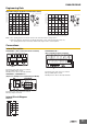
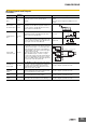
Signal name
Terminal
name
Description of operation Wiring
Power supply
input
A1, A2
Connect the power source to the A1 and A2
terminals.
Connect the power supply plus (24 VDC) to the A1 terminal.
Connect the power supply minus (GND) to the A2 terminal.
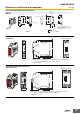
Safety input 1 T11, T12
To set the safety outputs in the ON state, the high
state signals must be input to both safety input 1
and safety input 2. Otherwise the safety outputs
cannot be in the ON state.
Corresponds to Safety
Category 2
Corresponds to Safety
Category 3 (without
short-circuit monitoring
between systems)
Safety input 2 T21, T22
Corresponds to Safety
Category 3 (Cross fault
detecting mode (for safety
inputs))
Non-contact
Door Switch
input
D1, D2,
D3, D4
All Non-contact Door Switch inputs connected to
the G9SX-NS must be ON as a required condition
for the safety outputs to be ON.
Otherwise the safety outputs cannot be in the ON
state.
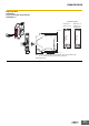
Feedback/reset
input
T31, T32,
T33
To set the safety outputs in the ON state, the ON
state signal must be input to T33.
Otherwise the safety outputs cannot be in the ON
state.
Auto reset
To set the safety outputs in the ON state, the signal
input to T32 must change from the OFF state to the
ON state, and then to the OFF state. Otherwise the
safety outputs cannot be in the ON state.
Manual reset
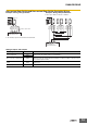
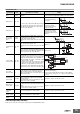
Logical AND
connection input
T41, T42,
T51, T52
A logical AND connection means that one unit (Unit
A) outputs a safety signal “a” to a subsequent unit
(Unit B) and Unit B calculates the logical AND (i.e.,
outputs the AND) of the signal “a” and safety signal
“b”, which is input to Unit B.
Thereby the logic of the safety output “b” is output.)
To set the safety outputs of the subsequent Unit in
the ON state, its logical AND connection preset
switch must be set to AND (enable) and the high
signal must be input to T41 of the subsequent unit.
Cross fault
detection input
Y1
Selects the mode for the failure detecting (cross
fault detecting) function for the safety inputs of
G9SX corresponding to the connection of the cross
fault detection input.
Keep Y1 open when using T11, T21. (Cross fault detecting
mode (for safety inputs))
Connect Y1 to 24 VDC when not using T11, T21. (Wiring
corresponding to category 2 or 3, or when connecting safety
sensors)
Instantaneous
safety output
S14, S24
Turns ON/OFF according to the state of the safety
inputs, feedback/reset inputs, and logical AND
connection inputs.
During OFF-delay state, the Instantaneous safety
outputs are not able to turn ON.
Keep these outputs open when not used.
OFF-delayed
safety output
S44, S54
OFF-delayed safety outputs.
The OFF-delay time is set by the OFF-delay preset
switch.
When the delay time is set to zero, these outputs
can be used as non-delay outputs.
Keep these outputs open when not used.
Logical AND
connection
output
L1
Outputs a signal of the same logic and at the same
time as the instantaneous safety outputs.
Keep these outputs open when not used.
Auxiliary
monitor output
X1
Outputs a signal of the same logic and at the same
time as the instantaneous safety outputs.
Keep these outputs open when not used.
Auxiliary error
output
X2 Outputs when the error indicator is lit or flashing. Keep these outputs open when not used.
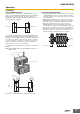
T11 T12 T21 T22
Y1
+24 V
+24 V
T11 T12 T21 T22
Y1
+24 V +24 V
+24 V
T11 T12 T21 T22
Y1
NC
D1 D2 D3 D4
White Black Brown Blue
Feedback loop
KM
+24 V
T31 T33T32
Feedback loop
KM
+24 V
T31 T33T32
Reset
Switch
G9SX-NS/NSA
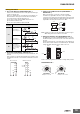
L1
A2
L1
T41 T42
A2
A2
G9SX-NS/NSA
Logical AND connection sig.
(1st layer)
Next unit (4 unit max.)
Next unit (5 layers max.)
T41 T42
L1
T41 T42
Logical AND connection sig.
(2nd layer)
Next unit (4 unit max.)
Input b
Input a
Output (a)
Output (a&b)
Unit B
Unit A
G9SX-NS/NSA
G9SX-NS/NSA