
Datasheet


D4BL
14
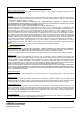
Solenoid Lock Models
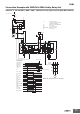
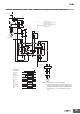
The solenoid lock locks the door only when power is supplied to the
solenoid. Therefore, the door will be unlocked if the power supply to
the solenoid stops. Therefore, do not use solenoid lock models for
machines that may be operating and dangerous even after the
machine stops operating.
Switch and Operation Key Mounting
Use four M5 screws and spring washers to mount the Switch and
Operation Key, and tighten the screws to a suitable torque.
To ensure safety, use screws that cannot be easily removed or
another means to prevent the Switch and Operation Key from easily
being removed.
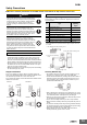
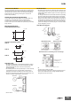
Mounting Dimensions
Switch Mounting Dimensions
Operation Key Mounting Holes
D4BL-K1
D4BL-K2
D4BL-K3
Operation Key
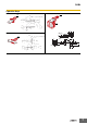
• The D4BL is provided with a shock-absorbing damper to protect
the D4BL from damage that may result from dropping the D4BL
during transportation. Be sure to remove the damper after
mounting the D4BL.
• The mounting tolerance of the Operation Key is ±0.3 mm vertically
or horizontally. Be sure to mount the D4BL correctly without
misalignment, otherwise the D4BL may soon break or wear out.
• Observe the specified insertion radius for the Operation Key and
insert it in a direction perpendicular to the key hole.
• Do not use the D4BS operation key.
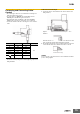
Head Direction
• The head can be mounted in four directions by loosening the four
screws holding the head. To remove the head, turn the head at the
surface mating with the Switch body by 45° as shown in figures (A)
and (B) below.
To change the direction of the head, make sure that the protruding
part of the rotating lever engages with the groove of the plunger.
Then turn the head clockwise or counterclockwise to the desired
direction. At that time, make sure that the groove of the plunger is
located under the rotating lever. If the direction of the head is not
set when the plunger is rotated by 45°, the groove of the plunger
presses the rotating lever. The head, plunger, or the built-in switch
may be damaged as a result.
Head Direction Changes
• Be sure to check the mechanical lock and solenoid release
functions when mounting the D4BL.
• If the head direction is changed, recheck the tightening torque of
each of screw. Make sure that no foreign materials will enter
through the key hole on the head.
100±0.1
74±0.1
Four, M5
20±0.1
Two, M5
40±0.1
Two, M5
30±0.1
Two, M5
Greater
than ±0.3
Greater
than ±0.3
Incorrect
Incorrect
(A) (B)
(45°)
(45°)
Left
Front
Back
Right
Head Bottom View Switch Top View
Operation plunger and
groove mechanism
Rotation lever and
protruding part
Switch body
Plunger (with groove)
Built-in switch
Normal Positions of Rotating Lever and Plunger
Rotating lever (with
protruding part)