E02E-E-01_safety guide.qxd 08-May-03 1:45 PM Page 1 Cat. No. E02E-E-01 Cat. No. E02E-E-01 Total solutions for industrial safety phone: + 31 - 23 56 81 300 – fax: + 31 - 23 56 81 388 – www.eu.omron.com SAFETY APPLICATION HANDBOOK SAFETY APPLICATION HANDBOOK OMRON EUROPE B.V. – Wegalaan 67-69 – 2132 JD Hoofddorp – The Netherlands Total solutions for industrial safety Advanced Industrial Automation Note: Specifications subject to change without notice. Cat. No.
SAFETY Safety Application Handbook © OMRON Europe B.V, 2003 Disclaimer OMRON reserve the right to alter or amend information contained in this handbook without prior notice and no responsibility can be accepted for errors or omissions. Safe installation and operation of OMRON products remains the responsibility of the user. The contained diagrams circuits and recommendations are only general information.
SAFETY Content page Chapter - 1 – 1.0 1.1 1.2 Background of this Handbook Necessity of machine safety Targeted Audience 1 1 1 Chapter - 2 – 2.0 2.1 2.2 2.3 2.3.1 2.4 2.5 Safety Basics European Legislation CE Certification Machine Directive Essential safety requirements Harmonised European standards Product liability 2 2 2 2 3 3 5 Chapter - 3 – 3.0 3.1 3.2 3.3 3.4 3.5 Ensure safety Risk assessment Categories Failure analysis Validation Documentation 6 6 7 8 10 11 Chapter - 4 – 4.0 4.1 4.2 4.3 4.3.
SAFETY Chapter - 6 – 6.0 6.1 6.1.1 6.1.2 6.2 6.3 6.3.1 6.3.2 6.3.3 6.
SAFETY 1.0 Background of this Handbook The European Union is one of the most important industrial areas worldwide. By doing their daily work 4,8% of workers become injured by industrial accidents (approximately 10 Million persons). Serious and lethal accidents happen to 0,17% of the workers (8000 person are killed per year). The reasons for these accidents on one hand are human negligence and insufficient safety of machinery on the other hand.
SAFETY 2.0 Safety Basics The Member States of the European Communities (EC) – this name was changed when the Treaty establishing the “European Union” (EU) was signed in the Maastricht On 7. Febr., 1992- unanimously agreed from the very beginning that the safety requirements for numerous products in the Member States (and also in the countries belonging to the European Economic Area – EEA) have to be harmonised. This common view point resulted in Article 100a.
SAFETY 2.3.1 Essential safety requirements The essential health and safety requirements laid down in this Directive are mandatory. However, taking into account the state of the art, it may not be possible to meet the objectives set by them. In this case, the machinery must as far as possible be designed and constructed with the purpose of approaching those objectives. The “danger zone” means any zone within and / or around machinery in which an exposed person is subject to a risk to his health or safety.
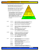
SAFETY The harmonized European safety standards have hierarchy: - - Type A standards (fundamental safety standards) give basic concepts, principles for design and general aspects that can be applied to all machinery. Type B standards (group safety standards) deal with one safety aspect or one type of safety – related device that can be used across a wide range of machinery.
SAFETY 2.5 Product liability The General Product Safety Directive and the Product Liability Directive are complementary regulations but their scope is not identical. For instance, the General Product Safety Directive states that even if a product does not conform to the directive and an action is taken against the manufacturer, the violation does not automatically mean the product is defective under the Product Liability Directive.
SAFETY 3.0 Ensure safety The responsible machine or process designer no longer considers the production requirements and adds safety systems later, but addresses the two issues as a whole. Legislation demands that the machine or process design meets the necessary safety standards and regulations – it is a legal requirement Different Types of machines will have different levels of associated risk these risk levels need to addressed for the whole machine life span.
SAFETY • Frequency of exposure. Step 4 Risk Evaluation & Reduction • • Determination of whether the level of risk is acceptable. Prioritisation of the implementation of control measures. Step 5 Risk Reduction • • • • Eliminate or reduce exposure to hazard as far as practical Reduce the probability and severity. Use safe guards and safety devices. Determine the performance and functional characteristics of the safety measures are suitable for the machine and its use.
SAFETY Category B Safety related parts of control systems and or their safety devices and their components must be designed, constructed, selected, assembled and combined in accordance with the relevant standards such that they can with stand expected influence. Category 1 The requirements of B shall apply. Well-tried components and safety principles shall be used.
SAFETY Selecting Parameter S: Severity of injury S1 and S2 In estimating the risk arising from a fault(s) in the safety-related parts of a control system only slight injuries (normally reversible) and serious injuries (normally irreversible including death) are considered. To make a decision the usual consequences of accidents and normal healing processes should be taken into account in determining S1 and S2, e.g.
SAFETY 3.4 Validation The purpose of validation is to determine the level of conformity of the safety-related parts of the control system to their specification within the overall safety requirements specification of the machinery. Validation consists of executing tests and applying analysis in accordance with the validation plan. The design of the safety-related parts of the control system shall be validated.
SAFETY 3.
SAFETY Once active operation of the emergency stop control has ceased following a stop command, that command must be sustained by engagement of the emergency stop device until that engagement is specifically overridden; it must not be possible to engage the device without triggering a stop command; it must be possible to disengage the device only by an appropriate operation, and disengaging the device must not restart the machinery but only permit restarting.
SAFETY According to EN 60204-1 the requirements for an emergency stop function are • it shall override all other functions and operations in all modes • power to the machine that can cause a hazardous condition(s) shall be remove as quick as possible without creating other hazards • reset shall not initiate a restart The standard divides applications into different stop categories. The choice of the category is depending on the risk assessment of the machine.
SAFETY 4.3.2 Two-channel input, category 3 Products: G9SB-3010, A22E 4 - 2-channel configuration - category 3 - auto reset S1: E-Stop pushbutton A22E KM1/KM2: Contactor M: 3 phase motor 4.3.
SAFETY 4.3.4 PLC integrated E-Stop with two-channel input, category 4, For compact system there is a possibility to have the safety circuit integrated in the PLC. The safety circuit itself is realized in hardwired technology. The benefit is that the PLC is able to monitor the status of all safety related signals and outputs directly without any additional effort. The module is able to ensure safety in systems up to category 4 ( EN954-1).
SAFETY 4.4 E-Stop and SLC configuration If the application requires same function for e-stop as in case of interruption of safety light curtain beams, you can use below circuit. The monitoring unit is able to monitor the OSSD outputs of the SLC and the E-Stop function. - SLC category 4 and E-Stop - category 4 - manual reset S4: Reset switch, S2: Diagnosis KM1/KM2: Contactor M: 3 phase motor E1: Power supply Dc 24V Note: 1. External relay monitoring and auxiliary output function are disabled 2.
SAFETY 4.5 Products for E-Stop Pushbuttons: OMRON can supply two series of e-stop pushbuttons, with 16mm (A165E) and 22mm (A22E) diameter panel cut-out. The A165E series is the one with the world shortest mounting depth of only 28.5mm below panel. A165E Series The A22E series advantages are • Easy mounting and removal • Wide variety of buttons are available • Up to IP65 protection Both received UL /CSA approvals and are in accordance with EN 60947-5-1 (positive opening contacts) and EN 418.
SAFETY 5.0 Door monitoring and interlocking Door monitoring and interlocking switches are one of the most important types of protective devices to prevent dangerous situations by taking power off from the machine. When it is decided to protect the machine with protective fences, we must be sure that, only way inside the dangerous area is through the guard. If the guard is opened, mechanically actuated position detector stops the machine.
SAFETY 5.2 Requirements for Door monitoring Door monitoring must ensure that the safety door is protecting the hazardous area as defined in the risk assessment ( EN1050). The sensors and the signal processing must comply with all required norms and directives. - Switches must be designed to withstand all expected and foreseeable stresses Switches must comply with safety standards especially direct opening contacts and safety door switches must be used.
SAFETY Operation key operated actuation The operation key operated switch is designed to prevent easy cheating of the switch. Dedicated operation key is needed every time. These switches can be used on sliding, hinged and lift-off guards. Mainly they are used in interlocking switches. Disadvantage in these switches is that it can be defeated by using a operation key which is not attached to the guard.
SAFETY G9SA-321T, time delayed output - category 4 for stop category 0 - category 3 for stop category 1 - manual reset S1: Safety switch with direct Opening (D4Dx, D4Bx) S2: Limit switch (D4DN, D4BN) S3: Reset button KM1/KM2: Contactor, M: motor Safety units for PLC integration CQM1-SF200, CS1W-SF200 - category 4 - 2 channel input - automatic reset - cross circuit detection S1: Limit switch (D4DN, D4BN) S2: Safety limit switch, safety door switch with direct Opening (D4Dx, D4Bx) KM1/KM2: Contactor, ( PLC u
SAFETY 5.5 Products for door monitoring and interlocking OMRON can supply a wide range of safety limit switches and safety door switches for monitoring and interlocking with of without locking function.
SAFETY D4BS Safety-door Switch • Metal body with IP67 degree of protection • 1- conduit or 3 conduit versions • Approved UL, CSA, BIA and SUVA • Conforms to EN standards corresponding to the CE marking • 3 different operation keys available Safety door switches with locking function: Keeps the protective guards locked until machine completely stops operation.
SAFETY 6.0 Two hand controlling To protect workers that are directly exposed to dangerous areas and need to access a hazardous zone, the usage of Two-hand control devices is an appropriate solution. Compared to a safety door that builds a barrier between user and hazard, the Twohand control forces the operator to keep both hands on the control actuating device while the machine is executing a potentially dangerous movement. Definition, EN 574 (1996) 3.
SAFETY One of the main requirements for electrical Two – Hand control units is the synchronous actuation. illustration 6.1 describes this function. Initiation of the 1. input signal Initiation of the 2. input signal Cessation of the input 1 st. hand 2 nd hand time t 0,5s time period of simultaneous actuation simultaneous actuation illustration 6.
SAFETY Prevention of defeat using hand and elbow of the same arm : - Separation of the control actuating devices by a distance equal to or more than 550mm Distance ≥ 550mm - Separation of the control actuating devices by the provision of one or more shields or an elevated area designed in such a way that the control actuating devices cannot be touched at the same time with both ends of measuring equipment consisting of a 300mm rigid bar not exceeding 5mm diameter and a 250mm cord attached to it.
SAFETY Prevention of defeat using the hand and other parts of the body: - Arrangement of the control actuating devices on a horizontal or nearly horizontal surface at least 1100mm above floor or level of access. ≥ 1100mm - Arrangement of the control actuating devices on a vertical or nearly vertical surface with protective collar(s) around the control actuating devices and/or shield(s). For this configuration use the test cone 6.1.
SAFETY 6.2 Requirement for 2-Hd controller A two hand control device complying to the machine directive 98/37/EC and EN 574 and is not a integral part of a machine, shall be labelled clearly and durably with the following details: - The name of the manufacturer and/or responsible supplier. - Manufacturer’s model or type reference. - Manufacturer’s serial number and year of manufacture. - Type of the two-hand control device according to clause 4, table 1 of EN 574.
SAFETY 6.3.
SAFETY 6.3.
SAFETY 6.4 OMRON Products for 2 Hand applications OMRON offers a wide range of safety products to realise a save and efficient solution. These products we recommend for usage in Two-hand control.
SAFETY 7. Light curtains Light curtains are a part of the electrical equipment used in machines which present risk of personal injury. It provides protection by causing the machine to go to a safe condition before a person can be placed in a hazardous situation. 7.
SAFETY EN 999 further on divides into three main applications based on the direction of approach to the detection zone: • Normal approach S = ( 2000mm/s x T ) + 8 (d-14mm) (1) d: detection capability of the sensor in mm ≤ 40mm This formula applies for all minimum distances of S ≤ 500mm. The minimum value of S shall not be < 100mm. If S is calculated > 500mm then formula (2) can be used. In this case the minimum value of S shall not be < 500mm.
SAFETY Summary general formula d ≤ 40mm 100mm ≤ S ≤ 500mm S > 500mm 40mm < d ≤ 70mm single beams S = K x T +C S = ( 2000mm/s x T ) + 8 (d -14mm) S = ( 1600mm/s x T ) + 8 (d -14mm) S = ( 1600mm/s x T ) + 850mm S = ( 1600mm/s x T ) + 1200mm 7.1.1 Examples safety distance Before calculating the safety distance S be sure that appropriate Type-C standard or the risk assessment for the relevant machine will allow the chosen sensor.
SAFETY Protection function: finger- and hand protection: Operator is close to the danger zone body protection: 1. access protection: presence of operator in danger zone visible all the time 2. presence detection: operator has to be detected all the time A finger or hand protection system is generally composed of a type 4, more frequently, or a type 2 safety light curtain (basing on the risk assessment result), and fixed guards.
SAFETY 7.2.2 Type 2 The norm EN 61496-2 requires a self-testing function for type 2 AOPDs. • • • • In case of a faulty condition the systems will detect this condition after the next test cycle The internal test cycle must be obtained in an appropriate time ( max. 150ms), depending on the safety requirement The effective aperture angle is specified to ± 5° from the beam-centre line. The safety level of Type 2 is equal to category 2 (EN954-1).
SAFETY 7.3.1 Type 4, multi beam To meet the requirements of EN 999 you can install single beams in the shown heights above floor. You can make it more simple by using multibeam sensors like Omron’s F3SH 4-beam safety sensor where the beam gap is already according to EN 999. 7.3.2 type 2, single beam For type 2 applications it is common to use single photoelectric sensors. This sensor can be combined with as much beams as required from the risk assessment.
SAFETY 7.4 Muting application The muting function is a temporary automatic suspension of a safety function(s) by safety-related parts of the control system, as described on the EN954-1 (Safety-related parts of control system). Muting application is very often used in combination with safety photoelectric sensors (ESPE, like safety light curtains).
SAFETY The muting function is possible for both type 2 and type 4 ESPE. The essential requirements for a particular application are described in type C norms. For example the essential requirements for palletiser are listed below, basing on the EN415-4: - Muting shall only occur during a limited time when the access to the dangerous zone is obstructed by the pallet. Muting should be completely automatic, in other words shall not depend from a manual operation of the operator.
SAFETY The mute sequence of the Omron F3SP-U_P-TGR control units is composed of two mute signals within bond times. The picture 3 illustrates graphically this concept: the delay between the second and the first mute signal, respectively B and A, must not exceed 3 seconds. Moreover, cause of the response time of the control unit, the delay between A and B can’t be lower than 30ms. Mute signals timing chart The duration of the mute state has a limit of 60 seconds, as requested by the norm.
SAFETY Example with two barriers composed of two single beam ESPE, four mute sensors and one F3SP-U1P-TGR control unit. Others characteritics of the F3SP control unit are the indicator, that is necessary for the correct working of the system, and the override function, that is activated by the pression of two pushbutton during the start-up of the unit. 7.5 Blanking application Fixed Blanking: Some applications have problems with mounting of the light curtain.
SAFETY 7.6 Single / double break application (EN 61496 Annex A, A8) If parts have to be put in and removed from a press machine manually then the safety light curtain is used not only for protection purpose but for initiation of the machine cycle as well. This will optimise the process and makes it safe. The control can be realised either in single break or double break mode. Single break: Double break: Actuation and de-actuation of the light curtain initiates machine movement.
SAFETY 7.7 Products for safety sensor applications OMRON offers a wide variety of safety sensors to protect your application.
SAFETY 8.0 Safe networks Due to technical progress it is possible to have safe data communication on serial networks. For standard communication Networks as DeviceNet, ASI, Ethernet etc. are established systems to have a high reliable communication. The connection of safety related information to a network was not possible in the past. Some European and international standards still insist on “hard wired“ realisation of safety systems.
SAFETY 8.2 CIP-safety, DeviceNet safety “CIP” represents the Control Information protocol of DeviceNet, Ethernet IP and some other bus systems. In 2002 three major automation companies ( OMRON, Rockwell Automation and Sick) developed the CIP safety extension. This CIP safety provides a open hybrid network that is the first media independent safety protocol. The network is a real open system, because the technology rights are transferred to ODVA (Open DeviceNet Vendor Association).
SAFETY 9.0 Glossary European standards defines technical principles and specifications to help designers and manufacturers in achieving safety in the design of machinery for professional and non-professional purposes. It may also be used for other technical products having similar hazards. 9.1 Definitions Hazard A source of possible injury or damage to health. Hazardous situation Any situation in which a person is exposed to a hazard or to hazards.
SAFETY Live part: A conductor or conductive part intended to be energised in normal use, including a neutral conductor, but, by convention, not a PEN conductor.
SAFETY Muting Temporary automatic suspension of a safety function(s) by safety-related parts of the control system Manual reset Function within the safety – related parts of the control system to manually restore Given safety functions before the re-starting of a machine. 9.2 Directives, Standards • Directives: Low Voltage Directive: Electromagnetic Compatibility Directive: Machinery Directive: • 73/23/EC issue date 19. Feb., 1973 89/336/EC issue date 03.
SAFETY EN 1088: Interlocking devices associated with guards – principles for design and selection EN 60204-1: Electrical equipment of machines, part 1: Specification for general Requirements EN 60947-1: Low-voltage switchgear and controlgear, part 1: General rules EN 60947-5-1: Low-voltage switch gear and controlgear – part 5-1: Control circuit devices and switching elements – Electromechanical circuit devices EN 61496-1: Electro – sensitive protective equipment, Part 1: General requirements and te
SAFETY 9.3 Literature, Links This section is to give you some additional sources for safety related topics. OMRON interactive safety guide ( UK, EN,DE,IT) Flash based guide through European legislation and standards Contains animated explanations for muting, blanking etc English sources: Safety of machinery in Europe (English Version) Beuth Verlag GmbH, Berlin.
SAFETY German sources: Leitfaden Maschinensicherheit in Europa (German Version) Beuth Verlag GmbH, Berlin.