
Datasheet


G-164 Safety Sensors / Components
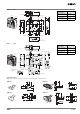
G9SA-301 (24 VAC/VDC) + D4NL-@@@G-@, @@@H-@, @@@J-@
(Solenoid Lock Type) + D4D-@520N Circuit Diagram
Control
circuit
Feedback loop
Operation
instruction
M
KM1
KM2
Motor controller
S1
Note: Lock release is possible at any time.
Therefore, do not use the solenoid lock type
in applications where the operator may be
exposed to danger when the guard opens.
Use the mechanical lock type instead.
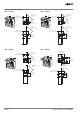
Timing Chart
Limit switch S1
S1: Safety Limit Switch
with direct opening mechanism
(D4N)
S2: Guard Lock Safety-door Switch
KM1 and KM2: Magnetic Contactor
M: 3-phase motor
Guard Lock Safety-door Switch S2
Operation signal
Lock signal
K1 and K2
(NC)
K1 and K2
(NO)
KM1 and KM2
(NC)
KM1 and KM2
(NO)
Guard opens
TH
SA
31
32
S2
OPEN
12
11
Lock signal
Operation signal