
Datasheet


G-166 Safety Sensors / Components
Correct Use
Operating Environment
• This Switch is for indoor use only. Do not use it outdoors. Other-
wise, it may malfunction.
• Do not use the Switch in the following locations:
•Locations subject to severe temperature changes
•Locations subject to high humidity levels or condensation
•Locations subject to severe shocks or vibrations
•Locations where the Switch may come in contact with metal dust,
oil, or chemicals
•Locations subject to thinner, detergent, or other solvents.
• Although the Switch itself is protected from dust or water penetra-
tion, ensure that foreign material does not penetrate through the
key hole on the head, otherwise Switch damage or malfunctioning
may occur.
• Do not use the Switch submerged in oil or water, or in locations
continuously subject to splashes of oil or water. Doing so may result
in oil or water entering the Switch interior. (The IP67 degree of pro-
tection specification for the Switch pertains to the amount of water
penetration after the Switch is submerged in water for a certain
period of time.)
Life Expectancy
The life expectancy of the Switch will vary with the switching condi-
tions. Before applying the Switch, test it under actual operating con-
ditions and be sure to use it at a switching frequency that will not
lower its performance.
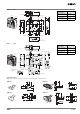
Operation Key
• Use the designated OMRON Operation Key with the Switch. Using
another Operation Key may result in Switch damage.
• Do not impose excessive force on the Operation Key when it is
inserted into the Switch or drop the Switch with the Operation Key
inserted. Otherwise, the Operation Key may be deformed or the
Switch may be broken.
Mounting
Tightening Torque
Be sure to tighten each screw of the Switch properly. Loose screws
may result in malfunction.
Switch and Operation Key Mounting
• Mount the Switch and Operation Key securely to the applicable
tightening torque with M4 screws.
]
• If the Switch is back-mounted, the release key can only be oper-
ated from the bottom and the indicator cannot be used.
• Use the designated OMRON Operation Key with the Switch. Using
another Operation Key may result in Switch damage.
• Ensure that the alignment offset between the Operation Key and
the key hole does not exceed 1 mm.
Head Direction
By removing the four screws of the head, the mounting direction of
the head can be changed. The head can be mounted in four direc-
tions.
Ensure that no foreign matter penetrates the interior of the Switch.
Securing the Door
When the door is closed (with the Operation Key inserted), it may be
pulled beyond the set zone because of, for example, the door’s
weight, or the door cushion rubber. Also, if a load is applied to the
Operation Key, the door may fail to unlock properly. Use hooks to
ensure that the door stays within the set zone (0.5 to 3 mm).
Type Tightening torque
Terminal screw 0.59 to 0.78 N·m
Cover mounting screw 0.49 to 0.69 N·m
Head mounting screw 0.49 to 0.59 N·m
Operation Key mounting screw 2.35 to 2.75 N·m
Switch mounting screw 0.49 to 0.69 N·m
Connector 1.77 to 2.16 N·m
Cap screw 1.27 to 1.67 N·m
Applying
weight
Dropping
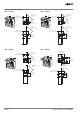
D4DS-K1/-K2 (horizontal/vertical mounting)
D4DS-K3 (adjustable mounting: horizontal)
D4DS-K5 (adjustable mounting: vertical)
40
±0.1
Two, M4
15
±0.1
Two, M4
Mounting Hole Dimensions
for Switch
Mounting Hole Dimensions
for Operation Key
Three, M4
79
±
0.1
32±
0.1
55±
0.1
41
±0.1
or, 43
±0.1
Two, M4
Operation Key
Set zone (0.5 to 3 mm)