
Datasheet

G-157D4NL
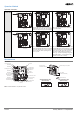
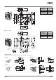
Connections
Indicator
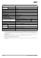
Internal Circuit Diagram
Circuit Connection Example
• Terminals 12 and 41 are connected internally and so connect termi-
nals 11 and 42 for safety-circuit input. (GS-ET-19)
• Connect terminals 21 and 22 and terminals 51 and 52 in series
when using as safety-circuit input (redundancy circuit for terminals
11 and 12 and terminals 41 and 42 above). Connect the terminals
individually when using as auxiliary-circuit input (e.g., terminals 21
and 22 for safety-door open/closed monitoring and terminals 51
and 52 for monitoring the lock status).
• In the connection example on the right, terminals 21 and 22 and
terminals 51 and 52 are used as auxiliary-circuit input.
• Direct opening contacts used as safety-circuit input are indicated
with the mark. Terminals 11 and 12 and terminals 21 and 22
are direct opening contacts.
• Connect the indicators in parallel to the auxiliary circuits or termi-
nals E1 and E2.
If an indicator is connected in parallel to a direct opening contact,
when the indicator breaks, a short-circuit current will be generated,
possibly resulting in an installation malfunction.
• Do not switch standard loads for more than 2 circuits at the same
time. Otherwise, the level of insulation may decrease.
• The 24-VDC solenoid has polarity. Be sure to connect terminals
with the correct polarity.
D
R
R
LED
Z
10 to 115 VAC/VDC
Constant-current diode
42
11
21
33
E1 (+)
O1 O2
12 41
51
52
22
34
E2 (−)
Indicator
(Orange)
Safety
circuit
Auxiliary
circuit
Auxiliary
circuit
Auxiliary
circuit