
Datasheet

G-158 Safety Sensors / Components
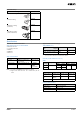
Operation Method
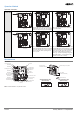
Operation Principles
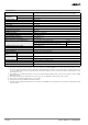
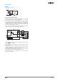
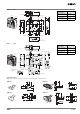
Nomenclature
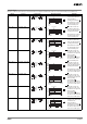
Structure
Note: Terminal numbers vary with the model.
Mechanical
lock models
When the Operation Key is inserted, it is
locked by the lock spring. The door will stay
locked even if there is a power interruption.
The solenoid is released only when the
lock is turned ON.
Solenoid
lock models
If the solenoid is OFF, the door will not be
locked when the Operation Key is inserted.
This means that the door can be opened
and closed easily when replacing work-
pieces or parts.
The door is locked only when the solenoid
is turned ON. This means that the door will
be unlocked if there is a power interruption
and so this model cannot be used in sys-
tems that would maintain a hazardous
state (e.g., systems requiring toxic gases,
high temperatures, or gears that would
continue to turn due to inertia).
Solenoid
Operation Key
Lock plate
Spring
OFF
OFF
ON
Solenoid
Operation Key
Lock plate
Spring
OFF
Plunger
OFF
ON
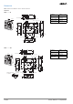
Special release key
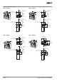
The head can be
mounted in 3 directions.
Two conduits
(horizontal and vertical)
Back-mounting is also possible.
Operation key hole
Terminal 42
Terminal 41
Shorting pin (12-41)
Terminal 12
Terminal 11
Door open/closed
detection switch
Terminal 21
Terminal 22
Terminal 31/33
Terminal 32/34
Release key
Conduit opening
(vertical)
Terminal 51/53
Terminal 52/54
Conduit opening
(horizontal)
Lock monitor switch
Terminal 02
Indicator
Terminal 01
Terminal E1 (+)
Terminal E2 (−)
Solenoid
UNLOCK LOCK UNLOCK LOCK
Standard Release Key
(Bottom View)
Special Release Key
(Bottom View)