
Datasheet

12 Inductive Sensors
Operation
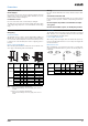
DC 3-wire models
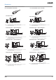
PNP Output
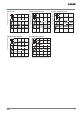
Operation mode Model Timing chart Output circuit
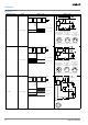
NO E2A-@-@-B1
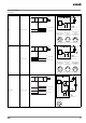
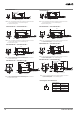
NC E2A-@-@-B2
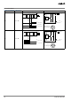
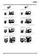
NO + NC E2A-@-@-B3
Sensing
object
(%)
100 0
Rated
sensing
distance
Sensing zoneNon-sensing zone
Proximity
Sensor
ON
OFF
ON
OFF
Yellow indicator
Control output
3
1
2
4
3
1
4
Load
Brown
Black
(See note 1.)
Blue
+V
0 V
Note 1: With M8 connector models, there is no output
reverse polarity protection diode.
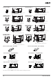
M12 Connector
Pin Arrangement
(See note 2.)
M8 connector
(3 pin)
Pin Arrangement
M8 Connector
(4 pin)
Pin Arrangement
(See note 2.)
Note 2: Pin 2 of the M12 connector and M8 connector is not
used.
Proximity
Sensor
main
circuits
1
2
4
3
(%)
100 0
Sensing
object
Rated
sensing
distance
Sensing zoneNon-sensing zone
Proximity
Sensor
ON
OFF
ON
OFF
Yellow indicator
Control output
3
1
2
4
Load
Brown
Black
(See note 1.)
Blue
+V
0 V
Note 1: With M8 connector models, there is no output
reverse polarity protection diode.
M12 Connector
Pin Arrangement
(See note 2.)
3
1
4
M8 connector
(3 pin)
Pin Arrangement
Note 2: Pin 4 of the M12 connector and M8 connector is not
used.
Proximity
Sensor
main
circuits
(M8 connector: )
M8 Connector
(4 pin)
Pin Arrangement
(See note 2.)
1
2
4
3
Sensing
object
(%)
100 0
Rated
sensing
distance
Sensing zoneNon-sensing zone
Proximity
Sensor
ON
OFF
ON
OFF
Yellow indicator
NO output
NC output
ON
OFF
Brown
+V
3
1
2
4
M12 Connector
Pin Arrangement
Black NO output
White
Load
Proximity
Sensor
main
circuits
Blue
2
3
Load
NC output
4
1
0 V