
Datasheet

13E2A
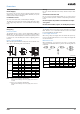
DC 3-wire models
NPN Output
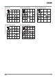
Operation mode Model Timing chart Output circuit
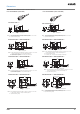
NO E2A-@-@-C1
NC E2A-@-@-C2
NO + NC E2A-@-@-C3
Sensing
object
(%)
100 0
Rated
sensing
distance
Sensing zoneNon-sensing zone
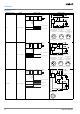
Proximity
Sensor
ON
OFF
ON
OFF
Yellow indicator
Control output
Load
Brown
Black
(See note 1.)
Blue
+V
0 V
Note 1: With M8 connector models, there is no output
reverse polarity protection diode.
Note 2: Pin 2 of the M12 connector and M8 connector is not
used.
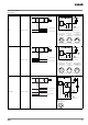
Proximity
Sensor
main
circuits
3
1
2
4
M12 Connector
Pin Arrangement
(See note 2.)
3
1
4
M8 connector
(3 pin)
Pin Arrangement
M8 Connector
(4 pin)
Pin Arrangement
(See note 2.)
1
2
4
3
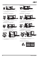
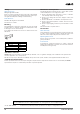
(%)
100 0
Sensing
object
Rated
sensing
distance
Sensing zoneNon-sensing zone
Proximity
Sensor
ON
OFF
ON
OFF
Yellow indicator
Control output
Load
Brown
Black
(See note 1.)
Blue
+V
0 V
Note 1: With M8 connector models, there is no output
reverse polarity protection diode.
Note 2: Pin 4 of the M12 connector and M8 connector is not
used.
Proximity
Sensor
main
circuits
(M8 connector: )
3
1
2
4
M12 Connector
Pin Arrangement
(See note 2.)
3
1
4
M8 connector
(3 pin)
Pin Arrangement
M8 Connector
(4 pin)
Pin Arrangement
(See note 2.)
1
2
4
3
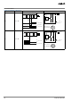
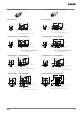
Sensing
object
(%)
100 0
Rated
sensing
distance
Sensing zoneNon-sensing zone
Proximity
Sensor
ON
OFF
ON
OFF
Yellow indicator
NO output
NC output
ON
OFF
Brown
+V
3
1
2
4
M12 Connector
Pin Arrangement
Black
White
Proximity
Sensor
main
circuits
Blue
2
3
Load
NC output
4
1
0 V
Load
NO output