
Datasheet

14 Inductive Sensors
DC 2-wire models
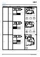
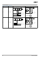
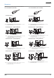
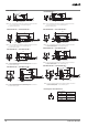
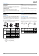
Output Circuit Diagrams (Operation)
Operation mode Model Timing chart Output circuit
NO E2A-@-D1
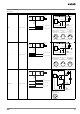
NC E2A-@-D2
Sensing
object
(%)
100 80 0
Rated
sensing
distance
Sensing zoneNon-sensing zone
Proximity
Sensor
ON
OFF
ON
OFF
ON
OFF
Yellow indicator
Red indicator
Control output
Load
Brown
Blue
+V
0 V
Load can be connected to +V or 0V side.
3
1
2
4
M12 Connector
Pin Arrangement
(%)
100 0
Sensing
object
Rated
sensing
distance
Sensing zoneNon-sensing zone
Proximity
Sensor
ON
OFF
ON
OFF
Yellow indicator
Control output
Load
Brown
Blue
+V
0 V
Load can be connected to +V or 0V side.
3
1
2
4
M12 Connector
Pin Arrangement