
Datasheet

18 Inductive Sensors
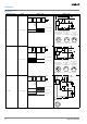
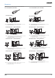
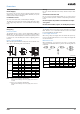
M8 Connector Models (Shielded) M8 Connector Models (Non-shielded)
Note: Please contact your OMRON sales representative for dimension drawings not listed here.
7
4
56
70
17
M12×1
M12×1
9.2 dia.
4
56
70
7
7
17
M12×1
M12×1
10
24
4
61
75
M18×1
M12×1
24
10
4
61
75
10
15.1 dia.
M18×1
M12×1
66
5
80
36
10
M30×1.5
M12×1
10
5
15
66
80
36
26.6 dia.
M30×1.5
Note: Operation indicator (yellow LED, 4×90°)
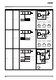
Note: Operation indicator (yellow LED, 4×90°)
Note: Operation indicator (yellow LED, 4×90°)
Note: Operation indicator (yellow LED, 4×90°)
Note: Operation indicator (yellow LED, 4×90°)
Note: Operation indicator (yellow LED, 4×90°)
E2A-M12LS04-M1-@@
E2A-S12LS04-M1-@
E2A-M18LS08-M1-@@
E2A-S18LS08-M1-@
E2A-M30LS15-M1-@@
E2A-S30LS15-M1-@
E2A-M12LN08-M1-@@
E2A-S12LN08-M1-@
E2A-M18LN16-M1-@@
E2A-S18LN16-M1-@
E2A-M30LN30-M1-@@
E2A-S30LN30-M1-@
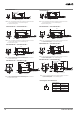
Two, clamping nuts
Indicator (See note.)
Two, clamping nuts
Indicator (See note.)
Two, clamping nuts
Indicator (See note.)
Two, clamping nuts
Indicator (See note.)
Two, clamping nuts
Indicator (See note.)
Two, clamping nuts
Indicator (See note.)
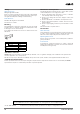
E2A-S08LS02-M1-@@
49
65
3
5
13
M8×1
M12×1
Note: Operation indicator (yellow LED, 4×90°)
E2A-S08LN04-M1-@@
6 dia.
3
5
49
65
6
13
M8×1
M12×1
Note: Operation indicator (yellow LED, 4×90°)
Two, clamping nuts
Indicator (See note.)
Indicator (See note.)
M8×1
M8×1
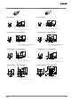
E2A-S08KS02-M5-@@/E2A-S08KS02-M3-@
E2A-S08KN04-M5-@@/E2A-S08KN04-M3-@
5.8 dia.
3
6
13
5
27
39
M8×1
M8×1
Note: Operation indicator (yellow LED, 4×90°)
Note: Operation indicator (yellow LED, 4×90°)
3
13
27
5
39
Two, clamping nuts
Two, clamping nuts
M8×1
M8×1
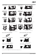
E2A-S08LS02-M5-@@/E2A-S08LS02-M3-@
E2A-S08LN04-M5-@@/E2A-S08LN04-M3-@
5.8 dia.
3
6
13
5
49
61
M8×1
M8×1
Note: Operation indicator (yellow LED, 4×90°)
Note: Operation indicator (yellow LED, 4×90°)
3
13
49
5
61