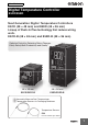
New Product Digital Temperature Controller E5CD/E5ED Next Generation Digital Temperature Controllers E5CD (48 × 48 mm) and E5ED (48 × 96 mm) Lineup of Push-In Plus technology that reduce wiring work. E5CD-B (48 × 48 mm) and E5ED-B (48 × 96 mm) Optimize Control by Detecting Status Changes. Easily Satisfy Both Productivity and Quality.
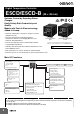
Digital Temperature Controller E5CD/E5CD-B (48 × 48 mm) Optimize Control by Detecting Status Changes. Easily Satisfy Both Productivity and Quality. Models with Push-In Plus technology Added to Lineup. • Automatic optimization of control for changes in systems (Adaptive Control). • Functions specialized for packaging machines 48 × 48 mm 48 × 48 mm Screw Terminal Blocks Push-In Plus Terminal Blocks (Temperature Sensors for Packaging Machines and E5CD E5CD-B Automatic Filter Adjustment).
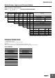
E5CD/E5CD-B Model Number Legend and Standard Models Model Number Legend Models with Screw Terminal Blocks E5CD-@@ 2 @ 6 M -@@@ (Example: E5CD-RX2A6M-000) A B C D E F Model A B C D E F Control outputs 1 and 2 No.
E5CD/E5CD-B Model Number Legend Models with Push-In Plus Terminal Blocks E5CD-@@ 2 @ B M -@@@ (Example: E5CD-RX2ABM-000) A B C D E F Model A B C D E F Control outputs 1 and 2 No.
E5CD/E5CD-B Optional Products (Order Separately) USB-Serial Conversion Cable Model E58-CIFQ2 Terminal Covers Front Covers Type Hard Front Cover Soft Front Cover Model Y92A-48H Y92A-48D (Cannot be used on a Push-In Plus terminal block type) Draw-out Jig Model E53-COV17 E53-COV23 (3pcs) * Note: The E53-COV10 cannot be used. Refer to page 14 for the mounted dimensions. * E53-COV23 are provided with the Digital Temperature Controller.
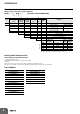
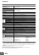
E5CD/E5CD-B Specifications Ratings Power supply voltage Operating voltage range Power consumption Sensor input Input impedance Control method Relay output Control output Auxiliary output Event input Voltage output (for driving SSR) Linear current output Number of outputs Output specifications Number of inputs External contact input specifications Number of outputs Output specifications Setting method Transfer Output Indication method Multi SP * Bank switching Other functions Ambient operating temp
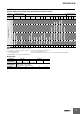
E5CD/E5CD-B Input Ranges Thermocouple/Platinum Resistance Thermometer (Universal inputs) Sensor type Platinum resistance thermometer Sensor specification Pt100 Infrared temperature sensor Thermocouple JPt100 K J T E L U N R S B C/W PLII 10 to 70°C 60 to 120°C 115 to 165°C 120 165 140 to 260°C 2300 2300 1800 1800 1700 1700 1700 1600 1500 1400 1300 Temperature range (°C) 1300 1300 1300 1200 1100 1000 900 850 850 850 800 700 600 600 500.0 500 500.0 500.0 400.
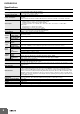
E5CD/E5CD-B Alarm Types Each alarm can be independently set to one of the following 17 alarm types. The default is 2: Upper limit. (see note.) Auxiliary outputs are allocated for alarms. ON delays and OFF delays (0 to 999 s) can also be specified. Note: In the default settings for models with HB or HS alarms, alarm 1 is set to a heater alarm (HA) and the Alarm Type 1 parameter is not displayed. To use alarm 1, set the output assignment to alarm 1.
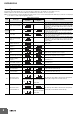
E5CD/E5CD-B *1. With set values 1, 4 and 5, the upper and lower limit values can be set independently for each alarm type, and are expressed as “L” and “H.” *2. Set value: 1, Upper- and lower-limit alarm Case 2 Case 1 Case 3 (Always ON) H<0, L<0 L H SP H<0, L>0 |H| < |L| H SP L H H>0, L<0 |H| > |L| SP L H<0, L>0 |H| ≥ |L| L SP H SP H L H>0, L<0 |H| ≤ |L| *3.
E5CD/E5CD-B Characteristics Indication accuracy (at the ambient temperature of 23°C) Thermocouple: (0.3% of indication value or 1°C, whichever is greater) 1 digit max. *1 Platinum resistance thermometer: (0.2% of indication value or 0.8°C, whichever is greater) 1 digit max. Analog input: 0.2% FS 1 digit max. CT input: 5% FS 1 digit max. Transfer output accuracy 0.3% FS max. Influence of temperature *2 Influence of EMS.
E5CD/E5CD-B USB-Serial Conversion Cable Connector specifications Power supply Power supply voltage Current consumption Output voltage Output current Windows XP/Vista/7/8/10 *1 CX-Thermo version 4.66 or higher (E5CD-B: version 4.67 or higher) E5@C-T Series, E5@C Series, E5CB Series, and E5@D Series 38,400 bps Computer: USB (type A plug) Digital Temperature Controller: Special serial connector Bus power (Supplied from USB host controller.)*2 5 VDC 450 mA max. 4.70.
E5CD/E5CD-B External Connections E5CD (Screw Terminal Blocks) Control output 1 E5CD-@@ 2 @ 6 M - @@@ Relay output 250 VAC, 3 A (resistive load) Voltage output (for driving SSR) 12 VDC, 21 mA Linear current output 0 to 20 mA DC 4 to 20 mA DC Load: 500 Ω max (1) (2) (3) (4) (5) ↑ Terminal type (6) The E5CD is set for a K-type thermocouple (input type = 5) by default. An input error (s.err) will occur if the input type setting does not agree with the temperature sensor. Check the input type.
E5CD/E5CD-B E5CD-B (Push-In Plus Terminal Blocks) E5CD-@@ 2 @ B M - @@@ Control output 1 Relay output 250 VAC, 3 A (resistive load) Voltage output (for driving SSR) 12 VDC, 21 mA Linear current output 0 to 20 mA DC 4 to 20 mA DC Load: 500 Ω max (1) (2) (3) (4) (5) ↑ Terminal type (6) The E5CD-B is set for a K-type thermocouple (input type = 5) by default. An input error (s.err) will occur if the input type setting does not agree with the temperature sensor. Check the input type.
E5CD/E5CD-B Nomenclature E5CD/E5CD-B Front panel Temperature unit Operation indicators No. 1 display PV or specified parameter Top View No. 2 display SP or specified parameter value Bar display Use the U D Keys to set the parameter. Press O Key once to go to Adjustment Level. Use S Key to change the digit (default setting). Press O Key for at least 3 seconds to go to Initial Setting Level. Top-panel Setup Tool port Use the M Key to change to another parameter.
E5CD/E5CD-B Accessories (Order Separately) USB-Serial Conversion Cable E58-CIFQ2 (2110) 263 250 1510 LED (RD) USB connector (type A plug) LED (PWR) Serial connector LED (SD) Terminal Covers (Cannot be used on a Push-In Plus terminal block type) 48 E53-COV17 48.8 22 9.1 Terminal Covers (Cannot be used on a Push-In Plus terminal block type) E53-COV23 (Three Covers provided.) 2 The Terminal Covers are provided with the Digital Temperature Controller.
E5CD/E5CD-B Current Transformers E54-CT1 21 Filler (epoxy) 15 5.8 dia. 7.5 Case 25 Thru-current (Io) vs. Output Voltage (Eo) (Reference Values) E54-CT1 or E54-CT1L 2.8 Maximum continuous heater current: 50 A (50/60 Hz) Number of windings: 4002 Winding resistance: 182 2.5 40 Output voltage (Eo) V (r.m.s.) 10.5 10 5 Two, 3.5 dia.
E5CD/E5CD-B E54-CT3 2.36 dia. 30 Filler (epoxy) 12 dia. 9 Case (PBT) Maximum continuous heater current: 120 A (50/60 Hz) (Maximum continuous heater current for an OMRON Digital Temperature Controller is 50 A.) Number of windings: 400±2 Winding resistance: 8±0.8 Output voltage (Eo) V (r.m.s.
E5CD/E5CD-B Adapter Y92F-45 Note: 1. Use this Adapter when the Front Panel has already been prepared for the E5B@. 2. Only black is available. 3. You cannot use the E58-CIFQ2 USB-Serial Conversion Cable if you use the Y92F-45 Adapter. To use the USB-Serial Conversion Cable to make the settings, do so before you mount the Digital Temperature Controller in the panel. 4. You cannot use it together with the Y92F-49 Adapter that is enclosed with the Controller. Fixture (Accessory) 76 69.6 to 77.6 4.
E5CD/E5CD-B Mounting Adapter Waterproof Cover Y92F-49 Y92A-48N 21.9 14 The Mounting Adapter is provided with the Digital Temperature Controller. Order this Adapter separately if it becomes lost or damaged. (2) 87.7 69 79.2 12 28.9 67.6 Front Cover Front Cover Y92A-48D Y92A-48H Note: This Front Cover cannot be used if the Waterproof Packing is installed. This Front Cover is hard type. Please use it for the mis-operation prevention etc. This Front Cover is soft type.
Digital Temperature Controller E5ED/E5ED-B (48 × 96 mm) Optimize Control by Detecting Status Changes. Easily Satisfy Both Productivity and Quality. Models with Push-In Plus technology Added to Lineup. • Automatic optimization of control for changes in systems (Adaptive Control). • Functions specialized for packaging machines (Temperature Sensors for Packaging Machines and Automatic Filter Adjustment). • Function specialized for water-cooled extruders (Watercooling Output Adjustment).
E5ED/E5ED-B Model Number Legend and Standard Models Model Number Legend Models with Screw Terminal Blocks E5ED-@@ 4 @ 6 M -@@@ (Example: E5ED-RX4A6M-000) A B C D E F Model A B C D E F Control outputs 1 and 2 No.
E5ED/E5ED-B Model Number Legend Models with Push-In Plus Terminal Blocks E5ED-@@ 4 @ B M -@@@ (Example: E5ED-RX4ABM-000) A B C D E F Model A B C D E F Control outputs 1 and 2 No.
E5ED/E5ED-B Optional Products (Order Separately) USB-Serial Conversion Cable Model E58-CIFQ2 Communication Conversion Cable Current Transformers (CTs) Hole diameter 5.8 mm 5.8 mm 12.0 mm 12.0 mm Model E54-CT1 E54-CT1L* E54-CT3 E54-CT3L* Model E58-CIFQ2-E Note: Always use this product together with the E58-CIFQ2. *Lead wires are included with these CTs. If UL certification is required, use these CTs.
E5ED/E5ED-B Specifications Ratings A in model number: 100 to 240 VAC, 50/60 Hz D in model number: 24 VAC, 50/60 Hz; 24 VDC Operating voltage range 85% to 110% of rated supply voltage Models with option selection of 000: 6.6 VA max. at 100 to 240 VAC, and 4.1 VA max. at 24 VAC or 2.3 W max. Power consumption at 24 VDC All other models: 8.3 VA max. at 100 to 240 VAC, and 5.5 VA max. at 24 VAC or 3.2 W max.
E5ED/E5ED-B Input Ranges Thermocouple/Platinum Resistance Thermometer (Universal inputs) Sensor type Platinum resistance thermometer Sensor specification Pt100 Infrared temperature sensor Thermocouple JPt100 K J T E L U N R S B C/W PLII 10 to 70°C 60 to 120°C 115 to 165°C 120 165 140 to 260°C 2300 2300 1800 1800 1700 1700 1700 1600 1500 1400 1300 Temperature range (°C) 1300 1300 1300 1200 1100 1000 900 850 850 850 800 700 600 600 500.0 500 500.0 500.0 400.
E5ED/E5ED-B Alarm Types Each alarm can be independently set to one of the following 17 alarm types. The default is 2: Upper limit. (see note.) Auxiliary outputs are allocated for alarms. ON delays and OFF delays (0 to 999 s) can also be specified. Note: In the default settings for models with HB or HS alarms, alarm 1 is set to a heater alarm (HA) and the Alarm Type 1 parameter is not displayed. To use alarm 1, set the output assignment to alarm 1.
E5ED/E5ED-B *1. With set values 1, 4 and 5, the upper and lower limit values can be set independently for each alarm type, and are expressed as “L” and “H.” *2. Set value: 1, Upper- and lower-limit alarm Case 2 Case 1 Case 3 (Always ON) H<0, L<0 L H SP H<0, L>0 |H| < |L| H SP L H H>0, L<0 |H| > |L| SP L H<0, L>0 |H| ≥ |L| L SP H SP H L H>0, L<0 |H| ≤ |L| *3.
E5ED/E5ED-B Characteristics Indication accuracy (at the ambient temperature of 23°C) Thermocouple: (0.3% of indication value or 1°C, whichever is greater) 1 digit max. *1 Platinum resistance thermometer: (0.2% of indication value or 0.8°C, whichever is greater) 1 digit max. Analog input: 0.2% FS 1 digit max. CT input: 5% FS 1 digit max. Transfer output accuracy 0.3% FS max.
E5ED/E5ED-B EMC EMI: Radiated Interference Electromagnetic Field Strength: Noise Terminal Voltage: EMS: ESD Immunity: Electromagnetic Field Immunity: Burst Noise Immunity: Conducted Disturbance Immunity: Surge Immunity: Voltage Dip/Interrupting Immunity: EN 61326-1 *6 EN 55011 Group 1, class A EN 55011 Group 1, class A EN 61326-1 *6 EN 61000-4-2 EN 61000-4-3 EN 61000-4-4 EN 61000-4-6 EN 61000-4-5 EN 61000-4-11 *6.
E5ED/E5ED-B USB-Serial Conversion Cable Connector specifications Power supply Power supply voltage Current consumption Output voltage Output current Windows XP/Vista/7/8/10 *1 CX-Thermo version 4.66 or higher (E5ED-B: version 4.67 or higher) E5@C-T Series, E5@C Series, E5CB Series, and E5@D Series 38,400 bps Computer: USB (type A plug) Digital Temperature Controller: Special serial connector Bus power (Supplied from USB host controller.)*2 5 VDC 450 mA max. 4.70.
E5ED/E5ED-B External Connections E5ED (Screw Terminal Blocks) Relay output 250 VAC, 5 A (resistive load) 3 4 3 4 OUT1 5 6 3 4 +Q − OUT1 5 6 RR QR Models with Voltage Output (for Driving SSR) and Relay Output OUT1 + − Q 3 4 5 Models with 2 Relay Outputs OUT1 R 3 4 5 OUT2 R 6 OUT2 R 6 (2) Auxiliary Outputs Auxiliary outputs 1, 2, 3, 4 7 8 9 10 11 12 A Models with 1 Voltage 1 linear current Output (for Driving SSR) Output R 5 6 (1) (2) (3) (4) (5) ↑ Terminal type (3) Input Power Suppl
E5ED/E5ED-B E5ED-B (Push-In Plus Terminal Blocks) Control output 2 Control output 1 Relay output 250 VAC, 5 A (resistive load) Voltage output (for driving SSR) 12 VDC, 40 mA When There Is a Control Output 2: 21 mA Linear current output 0 to 20 mA DC 4 to 20 mA DC Load: 500 Ω max (1) Control output QX Models with 1 Relay Output Models with 1 Voltage Output (for Driving SSR) 5 Relay output Models with 4 auxiliary outputs 250 VAC, 2 A (resistive load) OUT1 R 6 1 OUT1 +Q − 6 24 VAC/DC 1 * 2 3 3
E5ED/E5ED-B Isolation/Insulation Block Diagrams Sensor input and CT input Communications and event inputs Voltage output (for driving SSR), linear current output, and transfer output Power supply Relay output 1 Relay output 2 Auxiliary outputs 1, 2 Auxiliary outputs 3, 4 : Reinforced insulation : Functional isolation Note: Auxiliary outputs 1 and 2 and auxiliary outputs 3 and 4 are not insulated. Nomenclature E5ED/E5ED-B Front panel Temperature unit No.
E5ED/E5ED-B Dimensions (Unit: mm) Controllers E5ED (66) 62 4 44 1 48 110 96 Waterproof Packing Mounting Adapter (Accessory) (Accessory) 4 (1) 48 Terminal Covers (E53-COV24, accessory) (71.4) 67.4 44 110 96 Waterproof Packing (Accessory) 91 91 Mounting Adapter (Accessory) • Setup Tool ports are provided as standard feature. Use these ports to connect a computer to the Digital Temperature Controller.
E5ED/E5ED-B Accessories (Order Separately) USB-Serial Conversion Cable E58-CIFQ2 (2110) 263 250 1510 LED (RD) USB connector (type A plug) Serial connector LED (PWR) LED (SD) Conversion Cable E58-CIFQ2-E Conversion Cable Connected to the E58-CIFQ2 USB-Serial Conversion Cable (2,110) (1,510) 250 263 E58-CIFQ2 (Order separately) 1,510 Conversion Cable Note: Always use this product together with the E58-CIFQ2.
E5ED/E5ED-B Waterproof Cover Y92A-49N (for DIN 48 × 96) 21.9 (2) 131.7 67.6 28.9 Draw-out Jig (Cannot be used on a Push-In Plus terminal block type) Y92F-59 Use this Draw-out Jig to remove the interior body of the Digital Temperature Controller from the case to perform maintenance without removing the terminal wiring. 35.2 103.4 53.
E5ED/E5ED-B Current Transformers E54-CT1 21 Filler (epoxy) 15 5.8 dia. 7.5 Case 25 Thru-current (Io) vs. Output Voltage (Eo) (Reference Values) E54-CT1 or E54-CT1L 2.8 Maximum continuous heater current: 50 A (50/60 Hz) Number of windings: 4002 Winding resistance: 182 2.5 40 Output voltage (Eo) V (r.m.s.) 10.5 10 5 Two, 3.5 dia.
E5ED/E5ED-B E54-CT3 2.36 dia. 30 Filler (epoxy) 12 dia. 9 Case (PBT) Maximum continuous heater current: 120 A (50/60 Hz) (Maximum continuous heater current for an OMRON Digital Temperature Controller is 50 A.) Number of windings: 400±2 Winding resistance: 8±0.8 Output voltage (Eo) V (r.m.s.
E5CD/E5ED Operation Setting Levels Diagram This diagram shows all of the setting levels. To move to the advanced function setting level and calibration level, you must enter passwords. Some parameters are not displayed depending on the protect level setting and the conditions of use. Control stops when you move from the operation level to the initial setting level.
E5CD/E5ED Operation Parameter Flow This section describes the parameters set in each level. Pressing the M (Mode) Key at the last parameter in each level returns to the top parameter in that level. Hold down the M Key to move through the parameters in reverse. Some parameters may not be displayed depending on the model and other settings. Press the S Key*2 Power ON Starting in Manual Mode. Manual Control Level Press the S Key for at least 1 s. *1 C Press the O Key or the S Key for at least 1 s.
E5CD/E5ED Monitor/Setting Item Level 25 0 Monitor/Setting Item Display 1 S Monitor/Setting Item Display 2 S Monitor/Setting Item Display 3 S Monitor/Setting Item Display 4 S Monitor/Setting Item Display 5 Note: The monitor/setting items to be displayed is set in the Monitor/Setting Item 1 to 5 parameters (advanced function setting level). Press the O Key for at least 1 s.
E5CD/E5ED Error Displays (Troubleshooting) When an error occurs, the No. 1 display or No. 2 display shows the error code. Take necessary measure according to the error code, referring the following table. Display s.err Name Input error [[[[ Display range exceeded ]]]] e333 e111 Memory error Action Check the wiring for input to be sure it is wired correctly, not broken, and not shorted. Also check the input type. If there are no problems in the wiring or input type settings, cycle the power supply.
E5CD/E5ED Safety Precautions Be sure to read the precautions for all E5CD/E5ED models in the website at: http://www.ia.omron.com/. Warning Indications CAUTION Indicates a potentially hazardous situation which, if not avoided, may result in minor or moderate injury or in property damage. Precautions for Safe Use Supplementary comments on what to do or avoid doing, to use the product safely.
E5CD/E5ED Precautions for Safe Use Be sure to observe the following precautions to prevent operation failure, malfunction, or adverse affects on the performance and functions of the product. Not doing so may occasionally result in unexpected events. Do not handle the Digital Temperature Controller in ways that exceed the ratings. 1. The product is designed for indoor use only. Do not use or store the product outdoors or in any of the following places.
E5CD/E5ED 26.Do not place heavy objects on top of the USB-Serial Conversion Cable, bend the Cable beyond its natural bending limit, or pull on the Cable. Doing so may result in failure. 27.Make sure that the indicators on the USB-Serial Conversion Cable are operating properly. Depending on the application conditions, deterioration in the connectors and cable may be accelerated, and normal communications may become impossible. Perform periodic inspection and replacement. 28.
E5CD/E5ED Precautions during Operation E5ED/E5ED-B 1. It takes approximately two seconds for the outputs to turn ON from after the power supply is turned ON. Design the system (e.g., control panel) to allow for this delay. 2. Make sure that the Digital Temperature Controller has 30 minutes or more to warm up after turning ON the power before starting actual control operations to ensure the correct temperature display. 3.
E5CD/E5ED Drawing Out the Interior Body of the Digital Temperature Controller to Replace It You can use the Draw-out Jig to remove the interior body of the Digital Temperature Controller from the case to perform maintenance without removing the terminal leads. Use the Y92F-58 Draw-out Jig for the E5CD and the Y92F-59 Draw-out Jig for the E5ED. Check the specifications of the case and Digital Temperature Controller before removing the interior body from the case. (Drawout is not possible on the E5@D-B.) 3.
E5CD/E5ED Precautions when Wiring Connecting Stranded Wires • Separate input leads and power lines in order to prevent external noise. • Use crimp terminals when wiring the screw terminals. • Use the suitable wiring material and crimp tools for crimp terminals. • Tighten the terminal screws to a torque of 0.43 to 0.58 N·m. E5CD/E5ED (Screw Terminal Blocks) Wires Use the following procedure to connect the wires to the terminal block. 1.
E5CD/E5ED 3. Recommended Ferrules and Crimp Tools Recommended wires (Stranded wire/Solid wire) Use a flat-blade screwdriver to connect and remove wires. Use the following flat-blade screwdriver. The following table shows manufacturers and models as of 2015/Dec Stripping length (Ferrules not used) Recommended wire 0.25-1.5 mm2/AWG24-16 8 mm Side Front Recommended ferrules Applicable wire (mm2) (AWG) 0.25 24 0.34 22 0.5 20 0.75 18 1/1.25 18/17 1.25/1.
MEMO 50
Terms and Conditions Agreement Read and understand this catalog. Please read and understand this catalog before purchasing the products. Please consult your OMRON representative if you have any questions or comments. Warranties. (a) Exclusive Warranty. Omron’s exclusive warranty is that the Products will be free from defects in materials and workmanship for a period of twelve months from the date of sale by Omron (or such other period expressed in writing by Omron).
OMRON Corporation Industrial Automation Company Authorized Distributor: Kyoto, JAPAN Contact: www.ia.omron.com Regional Headquarters OMRON EUROPE B.V. Wegalaan 67-69, 2132 JD Hoofddorp The Netherlands Tel: (31)2356-81-300/Fax: (31)2356-81-388 OMRON ELECTRONICS LLC 2895 Greenspoint Parkway, Suite 200 Hoffman Estates, IL 60169 U.S.A. Tel: (1) 847-843-7900/Fax: (1) 847-843-7787 OMRON ASIA PACIFIC PTE. LTD. No.