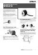
Incremental Rotary Encoder E6C2-C Please read and understand this catalog before purchasing the products. Please consult your OMRON representative if you have any questions or comments. IP64 Drip-proof Construction The E6C2-C incorporates a rubber-seal bearing cover of IP64 drip-proof construction thus ensuring ease of use in places with water dripping or sprayed oil.
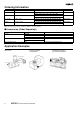
Ordering Information Supply voltage Output configuration 5 to 24 VDC NPN open collector output 12 to 24 VDC PNP open collector output Resolution (P/R) Model 10, 20, 30, 40, 50, 60, 100, 200, 300, 360, 400, 500, 600 E6C2-CWZ6C 720, 800, 1,000, 1,024, 1,200, 1,500, 1,800, 2,000 100, 200, 360, 500, 600 E6C2-CWZ5B 1,000, 2,000 5 to 12 VDC Voltage output 10, 20, 30, 40, 50, 60, 100, 200, 300, 360, 400, 500, 600 E6C2-CWZ3E 720, 800, 1,000, 1,024, 1,200, 1,500, 1,800, 2,000 5 VDC Line driver outpu
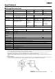
Specifications ■ Ratings/Characteristics Item E6C2-CWZ6C E6C2-CWZ5B Power supply voltage 5 VDC –5% to 24 VDC +15% 12 VDC –10% to 24 VDC +15% Current consumption (see note 1) 80 mA max. 100 mA max. Resolution 10, 20, 30, 40, 50, 60, 100, 200, 300, 360, 100, 200, 360, 500, 400, 500, 600, 720, 800, 1,000, 1,024, 600, 1,000, 2,000 P/R 1,200, 1,500, 1,800, 2,000 P/R E6C2-CWZ3E 5 VDC –5% to 12 VDC +10% E6C2-CWZ1X 5 VDC±5% 160 mA max.
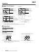
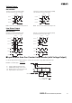
Operation ■ Output Circuit Diagram E6C2-CWZ6C E6C2-CWZ3E Brown Brown 5 VDC −5% to 24 VDC +15% 2 kΩ Black, white, orange Output signal (Black: Phase A, White: Phase B, Orange: Phase Z) NPN transistor Main circuit 35 mA max. 30 VDC max. 3.3 Ω (Shielded) Black, white, orange Output signal (Black: Phase A, White: Phase B, Orange: Phase Z) NPN transistor Main circuit 3.3 Ω Blue 20 mA max.
Voltage Output E6C2-CWZ3E Direction or resolution: Clockwise (CW) (As viewed from the end of the shaft) T (360°) Direction or resolution: Counterclockwise (CCW) (As viewed from the end of the shaft) CW T (360°) Phase A Phase A L H Phase B Phase B L H L L 1/4±1/8T (90°±45°) 1/4±1/8T (90°±45°) H H Phase Z CCW H H Phase Z L Note: Phase A is 1/4±1/8T faster than phase B. L Note: Phase A is 1/4±1/8T slower than phase B.
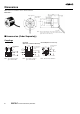
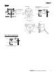
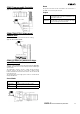
Dimensions Note: All units are in millimeters unless otherwise indicated. E6C2-CWZ@@ Origin of phase Z Three, M4 holes Depth: 7 mm 0 6 −0.021 dia. 50 dia. 0 25 −0.021 dia. 38 dia. (see note) Note: 2-m-long, oil-resistive PVC cable, 5-dia. (conductor crosssection: 0.2 mm2, insulator: 1.0 dia.) five conductors and shield (eight conductors for line driver use) ■ Accessories (Order Separately) Couplings E69-C68B E69-C06M (Metal Construction) (With Ends of Different Diameter) E69-C06B 22 5.5 (11) 5.5 24.
Flanges E69-FCA Mounting Bracket: (A set of three Brackets provided with the E69-FCA02) E69-FCA02 52 × 52 43±0.15 2 Four, 4.5-dia. holes Three, 4.5-dia. holes with 8.5-dia. screw-head holes Four, R3 5.5-dia. hole 25.2 ±0 0.05 -dia. hole 43±0.15 The flange is made of SPCC, t = 3.2 (18) 16 9 Three, 5.5 screw-head holes 8.5 dia. Two, C1 3.1 +0.1 0 8 25.2±0.1 dia. 56 dia. 38 dia. 16 (5.1) Note: Material: SPCC, t=3.2 Mounting Dimensions Panel 25 dia. 68±0.2 dia.
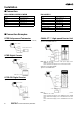
Installation ■ Connection E6C2-CWZ6C/-CWZ3E/-CWZ5B Color Brown E6C2-CWZ1X Terminal Color Terminal Power supply (+VCC) Brown Black Output phase A Black Output phase A White Output phase B White Output phase B Orange Output phase Z Orange Output phase Z Blue 0 V (common) Black/Red stripes Output phase A White/Red stripes Output phase B Power supply (+VCC) Orange/Red stripes Output phase Z Blue 0 V (common) Note: Receiver: AM26LS32 equivalent ■ Connection Examples H7ER Self-power
CQM1 Programmable Controller Reset Applicable Model: E6C2-CWZ6C The present count value can be reset with the soft-reset function or the AND of soft reset and phase Z input. CQM1 E63-WF5C Output Target value When the count value reaches the target value, the specified subroutine is executed. A maximum of 16 target values can be set. Range comparison E6C2-CWZ6C When the count value is within the range, the specified subroutine is executed. A maximum of 8 ranges can be set with upper and lower limits.
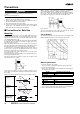
Precautions WARNING This products is not designed or rated for ensuring safety of persons. Do not use it for such purpose. When connecting or disconnecting the coupling, do not impose an excessive bending, pressing, or pulling force on the E6C2-C. When connecting the shaft of the Rotary Encoder with a chain timing belt or gear, connect the chain timing belt or gear with the shaft via the bearing and coupling as shown in the following illustration. Chain sprocket 1.
When extending the cord, select the kind of cord with care by taking the response frequency into consideration because the longer the cord is, the more the residual voltage increases due to the resistance of the cord and the capacitance between the wires. As a result, the waveform will be distorted. We recommend the line driver output type model if the cord needs to be extended. In order to reduce inductive noise, the cord must be as short as possible, especially when the signal is input to an IC.
WARRANTY OMRON’s exclusive warranty is that the products are free from defects in materials and workmanship for a period of one year (or other period if specified) from date of sale by OMRON. OMRON MAKES NO WARRANTY OR REPRESENTATION, EXPRESS OR IMPLIED, REGARDING NON-INFRINGEMENT, MERCHANTABILITY, OR FITNESS FOR PARTICULAR PURPOSE OF THE PRODUCTS. ANY BUYER OR USER ACKNOWLEDGES THAT THE BUYER OR USER ALONE HAS DETERMINED THAT THE PRODUCTS WILL SUITABLY MEET THE REQUIREMENTS OF THEIR INTENDED USE.