
Datasheet


E6C2-C Incremental Rotary Encoder 11
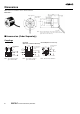
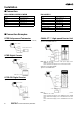
Connecting
When extending the cord, select the kind of cord with care by taking
the response frequency into consideration because the longer the
cord is, the more the residual voltage increases due to the resis-
tance of the cord and the capacitance between the wires. As a
result, the waveform will be distorted.
We recommend the line driver output type model if the cord needs to
be extended.
In order to reduce inductive noise, the cord must be as short as pos-
sible, especially when the signal is input to an IC.
Insert a surge absorber between the power supply terminals if there
is any surge.
A wrong pulse may be generated when the E6C2-C Rotary Encoder
is turned on or off. Do not use the connected device for 0.1 s after
the E6C2-C Rotary Encoder is turned on and for 0.1 s before the
E6C2-C Rotary Encoder is turned off.
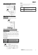
Cord Extension
The rise time of each output waveform will increase when the cord is
extended. This affects the phase difference characteristics of phases
A and B.
The available length of cord varies with the response frequency and
noise. It is safer to limit the length of cord to 10 m maximum. If a
longer cord of up to 100 m is required, use line driver output.
Note: Recommended Cord:
Cross section: 0.2 mm
2
with spiral shield
Conductor resistance: 92
Ω/km max. at 20°C
Insulation resistance: 5 M
Ω/km min. at 20°C
The rise time varies with the resistance of the cord and the kind of
cord as well as the length of the cord.
The residual output voltage will increase according to the length of
the cord.
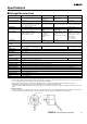
Conditions
Rotary Encoder: E6C2-CWZ6C
Load voltage: 5 VDC
Load resistance: 1 k
Ω (The residual output voltages were mea-
sured with a load current of 35 mA.)
Cord: Dedicated cord
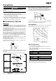
Conditions
Rotary Encoder: E6C2-CWZ5B
Load voltage: 12 VDC
Load current: 5 mA (The residual output voltages were mea-
sured with a load current of 35 mA.)
Cord: Dedicated cord
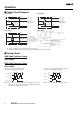
Preventing Miscounting
If the operation of the E6C2-C Rotary Encoder is stopped near a sig-
nal rising or falling edge, a wrong pulse may be generated, in which
case the E6C2-C Rotary Encoder will miscount. In such a case, use
an increment-decrement counter to prevent miscounting.
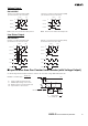
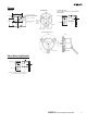
Extension of Line Driver Output
Be sure to use a twisted-pair cable to extend a line driver cord. Use
an RS-422A Receiver for the receiver side.
The twisted-pair wires as shown in the following illustration are suit-
able for RS-422A signal transmission. Normal mode noise can be
eliminated by twisting the wires because the generated electrical
forces on the lines cancel each other.
Be sure the E6C2-C Rotary Encoder is supplied with 5 VDC when a
line driver output is used. There will be an approximately 1-V voltage
drop if the cable length is 100 m.
Cable length L (m)
Residual output voltage V
OL
(V)
Output rise time t
LH
(µs)
Cable length L (m)
Residual output voltage V
OH
(V)
Output rise time t
HL
(µs)
E E
E
E
Twisted-pair wires