
Datasheet

8 E6C2-C Incremental Rotary Encoder
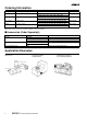
Installation
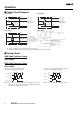
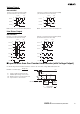
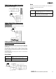
■ Connection
E6C2-CWZ6C/-CWZ3E/-CWZ5B E6C2-CWZ1X
Note: Receiver: AM26LS32 equivalent
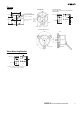
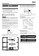
■ Connection Examples
H7ER Self-powered Tachometer
Applicable Model: E6C2-CWZ3E (with a resolution of 10 or 60 P/R)
H7BR Digital Counter
Applicable Model: E6C2-CWZ3E
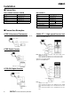
H7CR-CW Digital Counter
Applicable Model: E6C2-CWZ6C
C200H-CT@@ High-speed Counter Unit
Applicable model: E6C2-CWZ6C
Typical model: C200H-CT001-V1
Note: Apply the following connections if the power supply to the
E6C2-C is 5 or 24 V.
Phase A and Power Supply: 5 V to A19 and 24 V to B20
Phase B and Power Supply: 5 V to A17 and 24 V to B18
Applicable model: E6C2-CWZ5B
Typical model: C200H-CT021
Note: Apply the following connections if the power supply to the
E6C2-C is 12 or 24 V.
Phase A and Power Supply: 12 V to A8/B8 and 24 V to A9/B9
Phase B and Power Supply: 12 V to A12/B12 and 24 V to A13/
B13
Phase Z and Power Supply: 12 V to A16/B16 and 24 V to A17/
B17
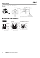
Color Terminal
Brown Power supply (+V
CC
)
Black Output phase A
White Output phase B
Orange Output phase Z
Blue 0 V (common)
Color Terminal
Brown Power supply (+V
CC
)
Black Output phase A
White Output phase B
Orange Output phase Z
Black/Red stripes Output phase A
White/Red stripes Output phase B
Orange/Red stripes Output phase Z
Blue 0 V (common)
E6C2-CWZ3E
5 to 12 VDC
Brown
Black
Blue
H7ER Digital Tachometer
H7BR Digital Counter
+12 V
0 V
Brown
Black
Blue
White
E6C2-C
Shielded
E6C2-CWZ6C
Black
White
Blue
Brown
12 VDC
(100 mA)
H7CR-CW
0 V
Encoder at 0 V
+12 V
0 V
Phase A
12-VDC power supply
+12 V
0 V
Phase B
Phase A
Phase B
+12 V
0 V
Phase A
12-VDC power supply
+12 V
0 V
Phase B
Phase Z
Phase Z Phase Z
0 V
5 to
24 VDC
Phase B Phase B
Phase A Phase A
Encoder at 0 V