
Datasheet


General-purpose Relay G2RS G-9
Electromechanical
relays
Technical and Environmental Properties
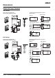
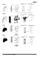
Two-way action test button
Typical information for reference only
The following data is provided as experimental and/or calculated data for reference only. These fall under the category of typical behaviour and
the operation of individual relays will vary according to the exact operating conditions
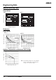
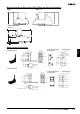
Multiple Contact DC Switching Capacity
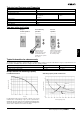
Load Reduction Factor
For AC inductive loads (such as solenoids, contactor coils, etc.) the
reduction factor corresponding to cos(p.f.) (cosine of power factor) is
multiplied by the rated current in order to identify the maximum allow-
able current. This approximation is not valid for loads with high inrush
currents such as electric motors or fluorescent lamps.
Switching capacity of DC resistive load
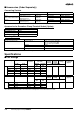
Properties 1-Pole and 2 Pole Model
DIN-railing Resistance Base 250
Environmental Protection RT 1
Flammability Class Base, Insulator, Spool
Case, Indicator,
Pushbutton
UL 94V-0
UL 94V-2
Pollution degree 2
Creepage Distance 8 mm
Clearance Distance 8 mm
Contact Material AgSnIn
Typical Operate / Release times 1 pole model 2 pole model
AC Type (operate / release time) 6 / 8 ms 6 / 10 ms
DC Type (operate / release time) 12 / 4 ms 11 / 15 ms
21
Pull down the test
button to the first
position, then press the
yellow button with an
insulated tool to operate
the contact.
Pull down the test button
to the second position.
(The contact is now in
the locked position).
For momentary
operation
For lock
operation
Relay in
normal operation
Switching Current (A)
Cos(p.f.)
1 0.8 0.6 0.4 0.2
1
0.8
0.6
0.4
Switching Current (A)
2 contacts
in series
10
1
0.1
G2R-1S
G2R-2-S
20 40 60 80 100 120 140 160 180 200 220
Switching Voltage (Vdc)