
Datasheet


K8AK-PH
4
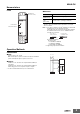
Connections
Terminal Diagram
Note: 1. Use the recommended ferrules if you use twisted wires.
Wiring Example
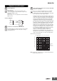
Timing Charts
●Phase Sequence and Phase Loss Operation
Diagram
Note: 1. The K8AK-PH1 output contacts are normally operative.
2. The Relay will not operate if the input voltage drops below
70% of the minimum input value because L1 and L2 are
also used to provide power.
3. Phase loss cannot be detected on the load side because
this detection is based on the voltage.
L1
L2
L3
11 12
Control Output
Relay output
250 VAC, 5 A (resistive load)
3-phase,
3-wire
power
supply
30 VDC, 5 A (resistive load)
14
Input voltage
Phase-to-phase voltage:
200 to 480 VAC
21
24
22
Relay Output
L1
L2
L3
21 24 22
11 12 14
L1
L3
11 12
14
21 24
22
L1
L2
L3
L2
3-phase
voltage
Motor
Alarm
load
Power supply
AC/DC
L1
L2
L3
L1
L3
L2
L3
L2
L1
L1
L2
L3
L2
L1
L3
11-14
21-24
Phase Loss Operation
Phase Sequence Operation
Input
Relay