
Datasheet


K8AK-PH
5
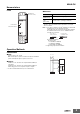
Nomenclature
Front
●Indicators
* The input across L1 and L2 is used for the internal power supply.
Therefore, the power indicator will not be lit if there is no input
across L1 and L2.
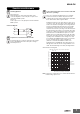
Note: 1. Use either a solid wire of 2.5 mm
2
maximum or a ferrule with
insulating sleeve for the terminal connection.
The length of the exposed current-carrying part inserted into
the terminal must be 8 mm or less to maintain dielectric
strength after connection.
Recommended ferrules
Phoenix Contact
• Al 1,5-8BK (for AWG16)
• Al 1-8RD (for AWG18)
• Al 0,75-8GY (for AWG18)
2. Tightening torque: 0.49 to 0.59 N·m
Operation Methods
Connections
●Input
Connect using L1, L2, and L3.
Make sure the phase sequence is wired correctly. The Unit will not
operate normally if the phase sequence is incorrect.
●Outputs
Terminals 11, 12, and 14 are the output terminals (SPDT) for
overvoltage.
Terminals 21, 22, and 24 are the output terminals (SPDT) for
undervoltage, phase loss, and phase sequence outputs.
* Use the recommended ferrules if you use twisted wires.
Power indicator
Relay status indicator
Terminal block
(See notes 1 and 2.)
Item Meaning
Power indicator
(PWR: Green)
Lit when power is being supplied *3.
Relay status indi-
cator
(RY: Yellow)
Lit when relay is operating (normally lit).
For 2.5 mm
2
or
smaller solid wires
For ferrules with
an insulation sleeve.
8 mm max. 8 mm max.
L1
L2
L3
L3L2L1
21
24
22
11
14
12
Load
Voltage input
Signal output
Relay signal
output