
Datasheet


K8DT-AS
4
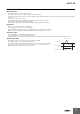
Connections
Terminal Diagram
Note: 1. Do not connect anything to terminals that are shaded in gray.
2. There is no polarity for the DC power supply input.
3. For the current input, you can input only from the C terminal and one other terminal.
4. Refer to Setting Ranges and Wiring Connections on the I1, I2, and I3 current input terminals.
5. The K8DT-AS3 is designed to be used in combination with the OMRON K8AC-CT200L Current Transformer (CT).
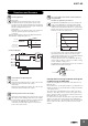
Wiring Example
Directly Inputting a Current Using a CT
Transistor Output
Note: Use copper wires with a rating of 75°C or an equivalent rating.
Inside
Inside
(1) Current Input
AS1
(2) Output
C: Relay Output T: Transistor Output
(3) Power Supply Voltage
A: 100 to 240 VAC
D: 24 VAC/DC
(No polarity)
500mA max.
20mA max.
100mA max.
AS2
AS3
CT
100A max.
200A max.
1A max.
5A max.
A1
I1
I3
14
A2
I2
11
12
C
CT
K8DT-AS1 C A
(1) (2) (3)
I1
I3
I2
C
I1
I3
I2
C
I1
I3
I2
C
14 11
12
A1 A2 A1 A2
14 11
DIP SW
DIP SW
Single-phase
power supply
Load
Power supply
voltage
A1
A2
Power
supply
AC/DC
A1
I1
I3
14
A2
I2
11
12
C
Single-phase
power supply
Load
Power supply
voltage
A1
A2
Power
supply
AC/DC
CT
DIP SW
A1
I1
I3
14
A2
I2
11
12
C
PLC
Single-phase
power supply
Load
Power supply
voltage
A1
A2
Power
supply
AC/DC
DIP SW
A1
I1
I3
14
A2
I2
11
C