
Datasheet


K8DT-AS
6
Operation Methods
Setting Ranges and Wiring Connections
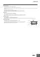
Connections
Input
Connect the input between the I1-COM, I2-COM, or I3-COM terminals, according to the input
current. Malfunctions may occur if the input is connected to unused terminals and the Unit will not
operate correctly.
For the K8DT-AS3, the I1 terminal is not used. For the K8DT-AS2, the I3 terminal is not used.
If using the OMRON K8AC-CT200L CT, connect to terminals k and l on the K8AC-CT200L.
(Terminals kt and lt are not used.)
Power Supply
Connect the power supply to terminals A1 and A2.
Outputs
For a relay output, the SPDT contacts are output on terminals 11, 12, and 14. For a transistor output,
the NPN output is on terminals 11 and 14.
Do not use the transistor output for control applications. It is designed only to output a signal when
an error is detected.
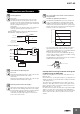
DIP Switch Settings
The reset method, drive output method, and operating mode are set using the DIP switch located on
the front of the Unit.
For the K8DT-AS@, SW1 is not used.
Note: Open the DIP switch cover to set the DIP switch.
Keep the DIP switch cover closed while the power supply to the Relay is ON.
Model Setting range Input type
Wiring
connections
K8DT-AS1
2 to 20 mA AC/DC Direct input I1-COM
10 to 100 mA AC/DC Direct input I2-COM
50 to 500 mA AC/DC Direct input I3-COM
K8DT-AS2
0.1 to 1 A AC/DC
Direct input or
commercially available
CT
I1-COM
0.5 to 5 A AC/DC I2-COM
K8DT-AS3
10 to 100 A AC * OMRON CT I2-COM
20 to 200 A AC * OMRON CT I3-COM
Note: The DC input terminals have no polarity.
* The K8DT-AS3 is designed to be used in
combination with the OMRON K8AC-CT200L
Current Transformer (CT). (Direct input is not
possible.)
Single-phase power
K8DT-AS3
K8AC-
CT200L
Current input
or
C (COM)
A1
A2
I1
I2
I3
Load
Power supply
voltage
11
14
11
14
l
k
12
Contact output
Transistor output
<For K8DT-AS3>
O
N
1
2
3
4
SW3
DIP switch pins
SW2
SW1
SW4
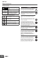
DIP Switch Functions
Note: All pins are set to OFF by default.
Pin
ON ❍
OFF ●
Resetting
method
Automatic reset
Not used.
❍ --- ---
Manual reset ● --- ---
Output drive
method
Normally closed --- ❍ ---
Normally open --- ● ---
Operating mode
Undercurrent --- --- ❍
Overcurrent --- --- ●
1
ON
OFF
2 3
4