
Datasheet
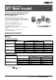
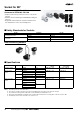

General-purpose Relay MY New model 7
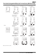
Typical information for reference only
The following data is provided as experimental and/or calculated data for reference only. These figures fall under the category of typical behaviour
and the operation of individual relays will vary according to the exact operating conditions.
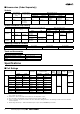
Typical Operate / Release Times 2-Pole model 4-Pole model
AC Type (operate / release time) 8 ms/8 ms 10 ms/10 ms
DC Type (operate / release time) 14 ms/4 ms 14 ms/6 ms
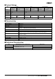
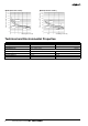
Load reduction Factor
For AC inductive loads (such as solenoids, contactors coils, etc.) the re-
duction factor corresponding to cos(p.f.) (cosine of the power factor) is
multiplied by the rated current in order to identify the maximum allowable
current. This approximation is not valid for loads with high inrush cur-
rents such as electric motors or fluorescent lamps.
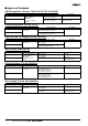
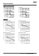
Multiple Contact DC Switching Capacity Effect of temperature on coil voltages
Switching capacity of DC resistive load MY2/4 Operating range (DC and AC type) vs ambient temperature
This graph can be used to estimate the number of contacts that can be
used to switch DC resistive loads
This graph shows the typical relationship between the maximum / mini-
mum coil and pick-up voltage and ambient temperature
Reduction factor
cos(p.f.)
1
0.8
0.6
0.4
1 0.8 0.6 0.4 0.2
0,1
1
10
100
20 40 60 80 100 120 140 160 180 200 220
Switching Voltage (Vdc)
Switching Current (A)
4 contacts
3 contacts
2 contacts
in series
MY2
MY4
2
1
0 1020304050607080
Ambient temperature (˚C)
0.5
1.0
1.5
2
U/Un
1: Max coil voltage permitted.
2: Min pick-up voltage with coil
at ambient temperature