
Datasheet


H3CR-A
7
■ Characteristics
Note: 1. The value is ±5% FS +100 ms to −0 ms max. when the C, D, or G mode signal of the H3CR-AP is OFF.
2. Refer to the Life-test Curve (Reference).
3. Contact output only.
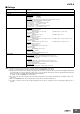
■ Life-test Curve (Reference)
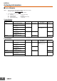
Accuracy of operating
time
±0.2% FS max. (±0.2%±10 ms max. in a range of 1.2 s or 3 s)
Setting error ±5% FS ±50 ms (See note 1)
Reset time Min. power-opening time: 0.1 s max.
Min. pulse width: 0.05 s (H3CR-A/-AS)
Reset voltage 10% max. of rated supply voltage
Influence of voltage ±0.2% FS max. (±0.2%±10 ms max. in a range of 1.2 s or 3 s)
Influence of temperature ±1% FS max. (±1%±10 ms max. in a range of 1.2 s or 3 s)
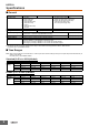
Insulation resistance 100 MΩ min. (at 500 VDC)
Dielectric strength 2,000 VAC (1,000 VAC for H3CR-A@S), 50/60 Hz for 1 min (between current-carrying metal parts and exposed non-
current-carrying metal parts)
2,000 VAC (1,000 VAC for H3CR-A@S), 50/60 Hz for 1 min (between control output terminals and operating circuit)
2,000 VAC, 50/60 Hz for 1 min (between contacts of different polarities)
1,000 VAC, 50/60 Hz for 1 min (between contacts not located next to each other)
2,000 VAC, 50/60 Hz for 1 min (between input and control output terminals and operation circuit) for H3CR-AP
Impulse withstand
voltage
5 kV (between power terminals) for 100 to 240 VAC/100 to 125 VDC, 1 kV for 24 to 48 VAC/12 to 48 VDC
5 kV (between current-carrying terminal and exposed non-current-carrying metal parts) for 100 to 240 VAC/100 to
125 VDC, 1.5 kV for 24 to 48 VAC/12 to 48 VDC and 24 to 48 VAC/VDC
Noise immunity ±1.5 kV (between power terminals) and ±600 V (between no-voltage input terminals), square-wave noise by noise
simulator (pulse width: 100 ns/1 μs, 1-ns rise)
Static immunity Malfunction: 8 kV
Destruction: 15 kV
Vibration resistance Destruction: 10 to 55 Hz with 0.75-mm single amplitude each in 3 directions for 2 hours each
Malfunction: 10 to 55 Hz with 0.5-mm single amplitude each in 3 directions for 10 minutes each
Shock resistance
Destruction: 1,000 m/s
2
3 times each in 6 directions
Malfunction: 100 m/s
2
3 times each in 6 directions
Ambient temperature Operating: −10°C to 55°C (with no icing)
Storage: −25°C to 65°C (with no icing)
Ambient humidity Operating: 35% to 85%
Life expectancy Mechanical: 20,000,000 operations min. (under no load at 1,800 operations/h)
Electrical: 100,000 operations min. (5 A at 250 VAC, resistive load at 1,800 operations/h) (See note 2)
EMC (EMI) EN61812-1
Emission Enclosure: EN55011 Group 1 class A
Emission AC Mains: EN55011 Group 1 class A
(EMS) EN61812-1
Immunity ESD: IEC61000-4-2
Immunity RF-interference: IEC61000-4-3
Immunity Burst: IEC61000-4-4
Immunity Surge: IEC61000-4-5
Immunity Conducted Disturbance: IEC61000-4-6
Immunity Voltage Dip/Interruption: IEC61000-4-11
Case color Light gray (Munsell 5Y7/1)
Degree of protection IP40 (panel surface)
Weight Approx. 90 g
10,000
5,000
1,000
500
100
01 23 45
Load current (A)
30 VDC L/R = 7 ms
250 VAC (cosφ = 0.4)
Switching operations (x 10
3
)
250 VAC/30
VDC (cosφ = 1)
Reference: A maximum current of 0.15 A can be switched at 125 VDC (cosφ = 1) and
a maximum current of 0.1A can be switched at 125V DC and L/R = 7ms.
In both cases, a life of 100,000 operations can be expected.
The minimum applicable load is 10 mA at 5 VDC (failure level: P).