
Datasheet


CSM_MK-S_DS_E_6_3
1
General-purpose Relays
MK-S (New Models)
New Super MK Relays.
Models with Latching Lever Added to
the Series.
• Same mounting and internal wiring as the previous Super
MK Relays
• Built-in mechanical indicator enables checking contact
operation.
• Two modes can be used to check circuits for models with
latching lever.
• Nameplate provided on models with latching lever.
• All materials are RoHS compliant.
• UL and IEC (TÜV) certification.
Features
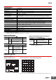
Models with Latching Lever
* The operation indicator is built in only on specified models.
Example of Applications of Models with Latching
Levers
Operation checks in relay sequence circuits
Operating Method for Latching Lever
Model Number Structure
Model Number Legend
1. Contact Form
2: DPDT
3: 3PDT
2. Terminals
P: Plug-in
3. Mechanical Indicator/Test Button
Blank: Mechanical indicator
I: Mechanical indicator and lockable test button
4. LED Indicator
Blank: Standard
N: LED indicator
5. Coil Polarity
Blank: Standard
1: Reverse polarity (DC coil only)
6. Surge Absorption
Blank: Standard
D: Surge absorber diode (DC coil only)
V: Surge absorber varistor (AC coil only)
7. Internal Connections
Blank: Standard
2 or 5: Non-standard connections (Refer to “Terminal
Arrangement and Internal Connection (Bottom View)”.)
8. Rated Voltage
(Refer to “Coil Ratings”.)
For the most recent information on models that have been certified for
safety standards, refer to your OMRON website.
Operation indicator *
Nameplate
Mechanical indicator
Latching lever
DC: Blue
AC: Red
Yellow
button
Relay in
Normal Operation
For Momentary
Operation
For Lock
Operation
Slide the latching lever
to the first position,
then press the yellow
button with an
insulated tool to
operate the contact.
Slide the latching
lever to the second
position.
(The contact is now in
the locked position.)
12 345 6 7
MKS@@@@@-@-@