
Datasheet


S8BA
5
Connections
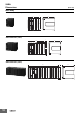
Block Diagrams
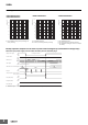
S8BA-24D24D@@@LF
* In normal operation, 24 VDC is output as-is for charging the battery and from the input power supply. If 24 VDC from the input power supply
drops, the operation automatically switches to backup operation, and 24 VDC is output from the battery.
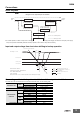
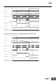
Input and output voltage time chart when shifting to backup operation
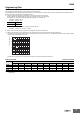
Connecting a cable to the input terminal block and the output terminal block
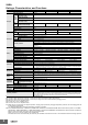
For details about the connectable sizes and recommended cable sizes, see the following table.
Connectable size
Cable
Solid wire 0.2 to 4.0 mm
2
Twisted pair 0.2 to 2.5 mm
2
Twisted pair with a bar terminal 0.25 to 1.5 mm
2
Stripped cable length 8 to 10 mm
Recommended
cable size
5 A
Solid wire/Twisted pair 0.5 mm
2
AWG AWG20
10 A
Solid wire/Twisted pair 0.75 mm
2
AWG AWG16
15 A
Solid wire/Twisted pair 1.25 mm
2
AWG AWG14
20 A
Solid wire/Twisted pair 2.0 mm
2
AWG AWG12
Temperature rating for recommended cable 90°C
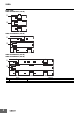
Diagram of the Input/output circuit block
FET
FET
Charge/Discharge
Battery
DC-DC converter
Normal operation
Backup operation
FET
24 VDC
Input
24 VDC
Output
Normal operation: OFF
Backup operation: ON
Normal operation: ON
Backup operation: OFF
Normal operation: ON
Backup operation: OFF
<4ms
<4ms
When high voltage sensitivity is set
*
When standard voltage sensitivity is set*
(Factory default)
When low voltage sensitivity is set*
Input voltage
<4ms
power failure or input voltage drop
DC22.2V (-7.5%)
DC21V (-12.5%)
DC20.4V (-15%)
<Measurement condition>
Switching power supply : S8VK-G48024
UPS : S8BA-24D24D240LF
Load : Rated load
When power failure occurs on the AC input side of the switching power supply
DC voltage
DC24V