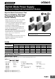
New Product Switch Mode Power Supply S8FS-G (15/30/50/100/150/300/600-W Models) Superior Basic Performance That Ensures Reliability. Wide Range of Standards Certification and Greater Usability. • Superior basic performance that ensures reliability Ambient temperatures up to 70°C, greater resistance to rusting with aluminum/stainless steel case, and applications at altitudes up to 3,000 m. • Certification for Global Standards North America: UL 508 (Listing)*, CSA C22.
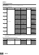
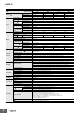
S8FS-G Ordering Information List of Models Note: For details on normal stock models, contact your nearest OMRON representative. With Cover/Direct Mounting Power ratings Input voltage 15 W 30 W 50 W 100 W 100 to 240 VAC 150 W 300 W 600 W Output voltage (VDC) Output current Built-in fan Model 5V 3A S8FS-G01505C 12 V 1.3 A S8FS-G01512C 15 V 1A S8FS-G01515C 24 V 0.65 A S8FS-G01524C 5V 6A S8FS-G03005C 12 V 3A S8FS-G03012C 15 V 2.4 A S8FS-G03015C 24 V 1.
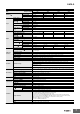
S8FS-G With Cover/DIN Rail Mounting Power ratings Input voltage 15 W 30 W 50 W 100 W 150 W 300 W 600 W 100 to 240 VAC Output voltage (VDC) Output current Built-in fan Model 5V 3A 12 V 1.3 A S8FS-G01512CD 15 V 1A S8FS-G01515CD 24 V 0.65 A S8FS-G01524CD S8FS-G01505CD 5V 6A S8FS-G03005CD 12 V 3A S8FS-G03012CD 15 V 2.4 A S8FS-G03015CD 24 V 1.5 A S8FS-G03024CD 5V 8A S8FS-G05005CD 12 V 4.3 A S8FS-G05012CD 15 V 3.5 A 24 V 2.
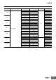
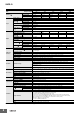
S8FS-G Specifications Power rating Item Efficiency * Inrush current * (for a cold start at 25°C) Output 24 V 84% typ. 85% typ. 200 VAC input 80% typ. 84% typ. 84% typ. 86% typ. 230 VAC input 80% typ. 84% typ. 84% typ. 86% typ. 1A 0.65 A 40 mVp-p max. 40 mVp-p max. 60 mVp-p max. Single phase, 85 to 264 VAC, 120 to 370 VDC 50/60 Hz (47 to 450 Hz) 100 VAC input 200 VAC input 0.32 A typ. 0.2 A typ. --- 100 VAC input 0.5 mA max. 200 VAC input 1 mA max. 100 VAC input 14 A typ.
S8FS-G Power rating Item Efficiency * Output 86% typ. 200 VAC input 81% typ. 86% typ. 88% typ. 88% typ. 230 VAC input 81% typ. 86% typ. 88% typ. 89% typ. 2.4 A 1.5 A 60 mVp-p max. 50 mVp-p max. 60 mVp-p max. Single phase, 85 to 264 VAC, 120 to 370 VDC 50/60 Hz (47 to 450 Hz) 100 VAC input 200 VAC input 0.72 A typ. 0.43 A typ. --- 100 VAC input 0.5 mA max. 200 VAC input 1 mA max. Inrush current * (for a cold start at 25°C) 100 VAC input 14 A typ. 200 VAC input 28 A typ.
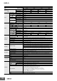
S8FS-G Power rating Item Efficiency * Output 86% typ. 200 VAC input 82% typ. 86% typ. 88% typ. 89% typ. 230 VAC input 82% typ. 86% typ. 88% typ. 89% typ. 3.5 A 2.2A 40 mVp-p max. 40 mVp-p max. 60 mVp-p max. Single phase, 85 to 264 VAC, 120 to 370 VDC 50/60 Hz (47 to 450 Hz) 100 VAC input 200 VAC input 1.1 A typ. 0.62 A typ. --- 100 VAC input 0.5 mA max. 200 VAC input 1 mA max. Inrush current * (for a cold start at 25°C) 100 VAC input 14 A typ. 200 VAC input 28 A typ.
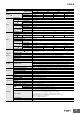
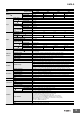
S8FS-G Power rating Output voltage Item Efficiency * Output Additional functions 15 V 24 V 79% typ. 84% typ. 85% typ. 87% typ. 200 VAC input 81% typ. 86% typ. 87% typ. 89% typ. 230 VAC input 81% typ. 86% typ. 87% typ. 89% typ. 7A 4.5 A 90 mVp-p max. 100 mVp-p max. 80 mVp-p max. Single phase, 85 to 264 VAC, 120 to 370 VDC Frequency * Input 12 V 100 VAC input Voltage range * Current * 100 W 5V 50/60 Hz (47 to 450 Hz) 100 VAC input 200 VAC input Power factor 2.1 A typ. 1.
S8FS-G Power rating Output voltage Item Efficiency *1 Output Additional functions 24 V 48 V 78% typ. 84% typ. 85% typ. 87% typ. 85% typ. 200 VAC input 81% typ. 87% typ. 88% typ. 89% typ. 88% typ. 230 VAC input 81% typ. 87% typ. 88% typ. 90% typ. 88% typ. 10 A 6.5 A 3.3 A 110 mVp-p max. 80 mVp-p max. 110 mVp-p max. 120 mVp-p max.
S8FS-G Power rating Item Efficiency * Output 82% typ. 200 VAC input 85% typ. 85% typ. 87% typ. 87% typ. 230 VAC input 85% typ. 86% typ. 87% typ. 87% typ. 14 A 7A 270 mVp-p max. 150 mVp-p max. 330 mVp-p max. Single phase, 85 to 264 VAC, 120 to 370 VDC 50/60 Hz (47 to 63 Hz) 100 VAC input 200 VAC input 4.2 A typ. 2.1 A typ. 0.9 min. 100 VAC input 0.5 mA max. 200 VAC input 1 mA max. Inrush current * (for a cold start at 25°C) 100 VAC input 14 A typ. 200 VAC input 28 A typ.
S8FS-G Power rating Item Efficiency * Output 88% typ. 200 VAC input 88% typ. 88% typ. 89% typ. 92% typ. 230 VAC input 88% typ. 88% typ. 90% typ. 92% typ. 27 A 13 A 170 mVp-p max. 280 mVp-p max. 340 mVp-p max. Single phase, 85 to 264 VAC, 120 to 350 VDC 50 /60 Hz(47 to 63 Hz) 100 VAC input 200 VAC input 7.7 A typ. 3.8 A typ. 0.9 min. 100 VAC input 0.5 mA max. 200 VAC input 1 mA max. Inrush current * (for a cold start at 25°C) 100 VAC input 14 A typ. 200 VAC input 28 A typ.
S8FS-G Ratings, Characteristics, and Functions Efficiency The value is when both rated output voltage and rated output current are satisfied. Voltage range Frequency Do not use an inverter output for the Power Supply. Inverters with an output frequency of 50/60 Hz are available, but the rise in the internal temperature of the Power Supply may result in ignition or burning. Current The value is when both rated output voltage and rated output current are satisfied.
S8FS-G Connections Block Diagrams S8FS-G015@@@ (15 W) S8FS-G030@@@ (30 W) S8FS-G050@@@ (50 W) AC(L) INPUT +V Fuse 250 VAC 15/30 W: 3.
S8FS-G S8FS-G300@@@ (300 W) +V AC(L) +V Fuse Noise filter 250 VAC 12 A HBC INPUT DC OUTPUT -V Rectifier AC(N) Inrush current protection Harmonic current suppression (power factor improvement) Smoothing circuit Rectifier smoothing circuit -V Drive circuit FAN Control circuit Over current detection circuit Rectifier smoothing circuit Voltage detection circuit Over voltage detection circuit Photocoupler Overheat detection circuit Overheat detection circuit +RC REMOTE CONTROL -RC Only Remo
S8FS-G Construction and Nomenclature Nomenclature S8FS-G015@@@ S8FS-G030@@@ S8FS-G050@@@ S8FS-G100@@@ S8FS-G150@@@ S8FS-G300@@@ S8FS-G600@@@ (1) (1) (2) (2) (3) (3) (9) (6) (6) (5) (4) (7) (6) (4) (7) (5) (8) (9) S8FS-G@@@24CE (3) (2) (1) (8) (9) S8FS-G@@@24C-R S8FS-G@@@24C-WR (2) (12) (11) (10) (9) (3) (4) (1) (1) (2) (3) (6) (4) (6) (5) (7) (6) (4) (7) (5) (8) (9) No.
S8FS-G Engineering Data Derating Curves Output Derating 120 100 W and 150 W Load rate (%) Load rate (%) 15 W, 30 W, 50 W, 300 W, and 600 W 100 120 100 80 80 75 60 60 40 40 20 25 20 0 -30 -20 -10 0 10 20 30 40 50 60 70 80 Ambient Temperature (°C) Note: At less than 100 VAC, derate the load at 1.3%/V. 0 -30 -20 -10 0 10 20 30 40 50 60 70 80 Ambient Temperature (°C) Note: At less than 100 VAC, derate the load at 1.3%/V.
S8FS-G This Power Supply can be used at an altitude of 3,000 m. Between 2,000 and 3,000 m, derate the load according to the following derating curve. 100 W and 150 W 120 100% 100 85% 45°C max. 50°C 60°C 80 70°C 70 Load rate (%) Load rate (%) 15 W, 30 W and 50 W 120 100% 100 87.5% 80 75 62.5% 50 25 20 20 0 500 1,000 1,500 2,000 2,500 3,000 3,500 0 Altitude (m) 120 100% 45°C max.
S8FS-G Engineering Data Remote Control Function (Only Remote control) The load and the Power Supply are automatically protected from overcurrent damage by this function. Overload protection is activated if the output current rises above 105 to 160% of the rated current. When the output current returns within the rated range overload protection is automatically cleared.
S8FS-G Dimensions (Unit: mm) Power Supplies 15 W and 30 W S8FS-G015@@C S8FS-G030@@C (14.3) 20.5 9.5 Panel mounting holes dimensions 55±0.5 8.2 Using the mounting holes in the Power Supply 3.5 Using the screw holes in the Power Supply 82±1 Side Mounting 40±0.5 40.5 Two, M3 (Depth 5 mm max.) 3.5 dia. Five, M3.5 88.5±0.5 5 Bottom Mounting 5 6.5 55±0.5 Two, M3 (Depth 3 mm max.) 18 Two, M3 Two, 3.5 dia. 74±0.5 87±0.5 3.5 87±0.5 17.5 S8FS-G015@@CD S8FS-G030@@CD Two, 3.5 dia. 88.5±0.
S8FS-G 50W S8FS-G050@@C (14.3) 20.5 9.5 55±0.5 Panel mounting holes dimensions 8.2 Using the mounting holes in the Power Supply 3.5 Using the screw holes in the Power Supply 97±1 55.5±0.5 Two, M3 (Depth 5 mm max.) Side Mounting 45.5 55.5±0.5 Two, M3 89±0.5 4.5 Bottom Mounting 5 Two, M3 6.5 87±0.5 18 74±0.5 3.5 36±1 29 18.5 Two, M3 (Depth 3 mm max.) Two, 3.5 dia. 87±0.5 99±1 3.5 dia. 55±0.5 89±0.5 3.5 dia. Five, M3.5 Two, 3.5 dia. 74±0.5 S8FS-G050@@CD (14.3) 9.5 5 117.
S8FS-G 100W S8FS-G100@@C (14.3) 9.5 Two, M3 (Depth 5 mm max.) 78 8.2 3.5 85.5±0.5 33±0.5 97±1 33 3.5 dia. Seven, M3.5 122.5±0.5 4.5 5.25 129±1 120±0.5 6.5 Three, M3 (Depth 6 mm max.) 3.5 3.5 dia. 28.5 13±0.5 18±0.5 38±1 28.5 19 32 77±0.5 10 Panel mounting holes dimensions Using the mounting holes in the Power Supply Using the screw holes in the Power Supply Two, 3.5 dia. Side Mounting 85.5±0.5 33±0.5 Two, M3 122.5±0.5 Bottom Mounting 13±0.5 120±0.5 S8FS-G100@@CD (14.3) 9.
S8FS-G S8FS-G100@@E Two, M3 (Depth 5 mm max.) 78 3.5 Input (L) Input (N) FG 97±1 33±0.5 Output (-) 85.5±0.5 Output (+) 33 3.5 dia. 122.5±0.5 4.5 5.25 129±1 120±0.5 6.5 Three, M3 (Depth 6 mm max.) 3.5 3.5 dia. 28.5 13±0.5 18±0.5 38±1 28.5 19 32 77±0.5 10 Panel mounting holes dimensions Using the mounting holes in the Power Supply Using the screw holes in the Power Supply Two, 3.5 dia. Side Mounting 85.5±0.5 33±0.5 Two, M3 122.5±0.5 Bottom Mounting 13±0.5 Three, 3.5 dia.
S8FS-G 150W S8FS-G150@@C (14.3) 9.5 24 78±0.5 3.5 8.2 84.5±0.5 Two, M3 (Depth 5 mm max.) 97±1 32 3.5 dia. 152.5±0.5 4.5 Seven, M3.5 5.5 159±1 Three, M3 (Depth 6 mm max.) 150±0.5 6.5 3.5 3.5 dia. 13±0.5 18±0.5 28.5 38±1 28.5 19 22 117±0.5 10.5 Panel mounting holes dimensions Using the mounting holes in the Power Supply Side Mounting Using the screw holes in the Power Supply Two, 3.5 dia. 84.5±0.5 78±0.5 Two, M3 152.5±0.5 Bottom Mounting 13±0.5 Three, M3 150±0.5 9.5±0.
S8FS-G S8FS-G150@@E 24 78±0.5 Input (L) Input (N) FG 3.5 97±1 84.5±0.5 Output (-) Output (+) 32 3.5 dia. 152.5±0.5 4.5 5.5 159±1 Two, M3 (Depth 5 mm max.) Three, M3 (Depth 6 mm max.) 150±0.5 6.5 3.5 dia. 28.5 3.5 13±0.5 18±0.5 38±1 28.5 19 22 10.5 117±0.5 Panel mounting holes dimensions Using the mounting holes in the Power Supply Side Mounting Using the screw holes in the Power Supply Two, 3.5 dia. 84.5±0.5 78±0.5 Two, M3 152.5±0.5 Bottom Mounting 13±0.5 Three, M3 150±0.
S8FS-G 300W S8FS-G300@@C 9.5 Two, M4 (Depth 5 mm max.) 64±0.5 28.5 Panel mounting holes dimensions 8.2 Using the screw holes in the Power Supply Side Mounting 102±1 Two, 4.5 dia. 64±0.5 Four, 4.5 dia. 50.5 Bottom Mounting 20±0.5 74±0.5 (14.1) Seven, M3.5 170±1 60 (3.5) 74±0.5 20±0.5 41±1 12 Four, M4 (Depth 5 mm max.) S8FS-G300@@CD (14.1) 200.7±1 5 8.2 9.5 53.5 48.5 Seven, M3.5 4.8 (Sliding: 7.5 max.) 42.2±1 Note: Use a metal DIN Rail when mounting a 300-W model to a DIN Rail.
S8FS-G 600W S8FS-G600@@C Four, M4 (Depth 5 mm max.) Four, M4 9.7 20.5 11 100±0.5 120±1 9.5 8.2 10 Three, M3.5 24 150±0.5 (3.7) (16.1) 190±1 38±0.5 61±1 12.5 24 150±0.5 (14.1) Four, M4 (Depth 5 mm max.) Panel mounting holes dimensions Using the screw holes in the Power Supply Four, 4.5 dia. Side Mounting 100±0.5 150±0.5 Bottom Mounting 38±0.5 Four, 4.5 dia. 150±0.5 S8FS-G600@@CD (16.1) Four, M4 220.7±1 10.8 5 9.7 62.5 20.5 8.2 9.5 57.5 (14.1) Three, M3.5 3.6 (Sliding: 6.3 max.
S8FS-G Mounting Brackets (Order Separately) Use the Front-mounting Brackets together with DIN Rail-mounting Power Supplies (S8FS-G@@@@@CD). Power rating Mounting direction Model 15 W, 30 W, 50 W 100 W, 150 W and 300 W Front-mounting S82Y-FSG-30F 600 W Front-mounting S82Y-FSG-60F S82Y-FSG-30F Two, 4.5±0.1 dia 35 40 25 (ends) (R1.5) 1 27 7.3 (ends) 35±0.1 57 t=1.2 S82Y-FSG-60F Two, 4.5±0.1 dia 35 40 25 (ends) (R1.5) 1 35±0.1 48 7.3 (ends) 57 t=1.
S8FS-G DIN Rail (Order Separately) (Unit: mm) Mounting Rail (Material: Aluminum) PFP-100N PFP-50N 7.3±0.15 4.5 35±0.3 15 25 10 25 25 10 1,000 (500) * 27±0.15 15(5) * 25 1 * Values in parentheses are for the PFP-50N. Mounting Rail (Material: Aluminum) PFP-100N2 16 4.5 35±0.3 27 15 25 10 25 25 10 1,000 25 15 24 29.2 1 1.5 End Plate PFP-M 10 6.2 M4×8 panhead screw 1.8 1 50 1.8 35.5 35.5 11.5 10 M4 spring washer 1.3 4.
S8FS-G Safety Precautions Refer to Safety Precautions for All Power Supplies. Warning Indications CAUTION Indicates a potentially hazardous situation which, if not avoided, may result in minor or moderate injury or in property damage. Precautions for Safe Use Supplementary comments on what to do or avoid doing, to use the product safely.
S8FS-G Mounting • Use the following material for the wires to be connected to the S8FS-G to prevent smoking or ignition caused by abnormal loads. S8FS-G015@@@ to 150@@@ 20 mm min. 20 mm min. Terminals and Wiring (Screw terminal block type) Terminals Model 20 mm min. 20 mm min. S8FS-G015@@@ Input S8FS-G300@@@ and S8FS-G600@@@ 20 mm min. AWG12-20 S8FS-G150@@@ to 600@@@ AWG12-16 S8FS-G03024@ 20 mm min. AWG12-22 S8FS-G030@@@ to 100@@@ S8FS-G01512@ to 01524@ 20 mm min.
S8FS-G Parallel Operation • The output voltage adjuster (V. ADJ) may possibly be damaged if it is turned with unnecessary force. Do not turn the adjuster with excessive force. • After completing output voltage adjustment, be sure that the output capacity or output current does not exceed the rated output capacity or rated output current. Parallel operation is used when the output current from one Power Supply is insufficient for the load.
S8FS-G Backup Operation Charging a Battery Backup operation is possible if you use two Power Supplies of the same model. Even if one Power Supplies fails, operation can be continued with the other Power Supply. Make sure that the maximum load does not exceed the capacity of one Power Supply. Connect the S8VK-R or external diodes as shown in the following figure for backup operation. Refer to the S8VK-R datasheet (Cat. No.: T059) for information on using the S8VK-R.
S8FS-G Period and Terms of Warranty Warranty Period The Power Supply warranty is valid for a period of three years from the date of shipment from the factory. Terms of Warranty The warranty is valid only for the following operating conditions. 1. Average ambient operating temperature of the Power Supply: 40°C max. (See note.) 2. Average load rate of 80% max. (See note.) 3. Mounting method: Standard mounting 4. Rated input voltage Note: The maximum ratings must be within the derating curve.
Terms and Conditions Agreement Read and understand this catalog. Please read and understand this catalog before purchasing the products. Please consult your OMRON representative if you have any questions or comments. Warranties. (a) Exclusive Warranty. Omron’s exclusive warranty is that the Products will be free from defects in materials and workmanship for a period of twelve months from the date of sale by Omron (or such other period expressed in writing by Omron).
OMRON Corporation Industrial Automation Company Authorized Distributor: Kyoto, JAPAN Contact: www.ia.omron.com Regional Headquarters OMRON EUROPE B.V. Wegalaan 67-69, 2132 JD Hoofddorp The Netherlands Tel: (31)2356-81-300/Fax: (31)2356-81-388 OMRON ELECTRONICS LLC 2895 Greenspoint Parkway, Suite 200 Hoffman Estates, IL 60169 U.S.A. Tel: (1) 847-843-7900/Fax: (1) 847-843-7787 OMRON ASIA PACIFIC PTE. LTD. No.