
Datasheet


L-36 Switch Mode Power Supply S8TS
Precautions
!WARNING
Do not attempt to take any Block apart or touch the interior of a
Block while the power is being supplied. Doing so may result in
electric shock.
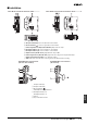
Do not link or separate any Blocks while the power is being sup-
plied. Doing so may result in electric shock.
Do not remove the connector cover on unused Bus Line Connec-
tors. Doing so may result in electric shock.
Close the terminal covers before use. Not doing so may result in
electric shock.
!Caution
When linking Blocks, lock the sliders and track stoppers.
When linking Blocks, wire the input line for 1 Block only. Other-
wise, inputs may be shorted internally resulting in damage to the
Blocks.
The tightening torque for terminal screws is 1.08 N·m. The tighten-
ing torque for connector screws and screw flanges is 0.30 N·m.
Loose screws may result in fire.
Do not touch the Power Supply while power is supplied or imme-
diately after power is turned OFF. The Power Supply becomes hot
and touching it may result in injury.
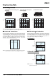
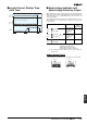
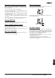
Mounting
To improve the long-term reliability of devices, give due consideration
to heat dissipation when mounting. With the S8TS, heat is dissipated
by natural convection. Mount Blocks in a way that allows convection
in the atmosphere around them.
*1. Convection of air
*2. 75 mm min.
*3. 75 mm min.
*4. 10 mm min.
When cutting out holes for mounting, make sure that cuttings do not
enter the interior of the products.
Wiring
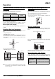
Be sure to wire I/O terminals correctly. When tightening the termi-
nals, do not exert a force of 100 N or more on terminal blocks or con-
nector terminals.
With Blocks with connector terminals, the current for 1 terminal must
not exceed 7.5 A. If a higher current is required, use 2 terminals.
Recommended Wire Size for Single
Operation
Recommended Wire Size for Parallel
Operation
Blocks with Connector Terminals
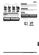
• When using Blocks with connector terminals, the current for
1 terminal must not exceed 7.5 A. If a higher current is required,
use 2 terminals.
• Do not insert/remove AC input connectors or DC output connector
more than 20 times.
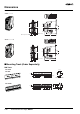
Installation Environment
Do not use the Power Supply in locations subject to shocks or vibra-
tions. Be sure to mount End Plates (PFP-M) on both ends of the
Power Supply. Install the Power Supply well away from any sources
of strong, high-frequency noise.
*1 *1
*1
*4
*1
*2
*3
Model Recommended wire size
S8TS-06024
S8TS-03012
AWG 14 to 20 (cross-sectional area: 0.517
to 2.081 mm
2
)
S8TS-02505 AWG 14 to 18 (cross-sectional area: 0.823
to 2.081 mm
2
)
S8TS-06024F
S8TS-03012F
AWG 12 to 20 (cross-sectional area: 0.517
to 3.309 mm
2
)
S8TS-02505F AWG 12 to 18 (cross-sectional area: 0.823
to 3.309 mm
2
)
Model Recommended wire size
S8TS-06024
S8TS-03012
For 2 Units con-
nected in paral-
lel
AWG 14 to 18 (cross-sectional ar-
ea: 0.823 to 2.081 mm
2
)
For 3 Units con-
nected in paral-
lel
AWG 14 to 16 (cross-sectional ar-
ea: 1.309 to 2.081 mm
2
)
For 4 Units con-
nected in paral-
lel
AWG 14 (cross-sectional area:
2.081 mm
2
)
S8TS-06024F
S8TS-03012F
For 2 Units con-
nected in paral-
lel
AWG 12 to 18 (cross-sectional ar-
ea: 0.823 to 3.309 mm
2
)
For 3 Units con-
nected in paral-
lel
AWG 12 to 16 (cross-sectional ar-
ea: 1.309 to 3.309 mm
2
)
For 4 Units con-
nected in paral-
lel
AWG 12 to 14 (cross-sectional ar-
ea: 2.081 to 3.309 mm
2
)