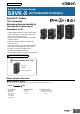
New Product Switch Mode Power Supply S8VK-X (60/120/240/480-W Models) EtherNet/IP, Modbus TCP-Compatible Maximizing System Availability Through the Connecting of Equipment to IoT • Product replacement time, output voltage, output current, and more are acquired on the network and can be managed all at once • Product status can be checked on-site using the indication monitor • Operation possible at ambient temperatures from -40 to 70°C • Power Boost function at 150% (240 and 480 W) • Side-by-side mounting p
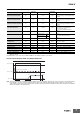
S8VK-X Ordering Information Note: For details on normal stock models, contact your nearest OMRON representative. With Indication Monitor Power rating 90 W 120 W 240 W 480 W Rated input voltage Rated output voltage (DC) Rated output current Maximum boost current 24 V 3.
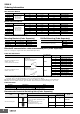
S8VK-X Ratings, Characteristics, and Functions Power rating 30 W Rated output voltage Item Indication monitor Efficiency * Inrush current * None 85% typ. 85% typ. 77% typ. 86% typ. 86% typ. Single-phase, 85 to 264 VAC, 90 to 350 VDC, 265 to 300 VAC (1 second) 50/60 Hz (47 to 450 Hz) 115 VAC input 0.53 A typ. 0.99 A typ. 1.1 A typ. 230 VAC input 0.32 A typ. 0.61 A typ. 0.67 A typ. --115 VAC input 0.5 mA max. 230 VAC input 1 mA max. 115 VAC input 16 A typ. 230 VAC input 32 A typ.
S8VK-X Power rating 90 W Rated output voltage 24 V Item Indication monitor 115 VAC input Efficiency * 230 VAC input Voltage range * Input conditions Inrush current * None 86% typ. 87% typ. 90% typ. 90% typ. 87% typ. 88% typ. 92% typ. 92% typ. 50/60 Hz (47 to 450 Hz) 50/60 Hz (47 to 63 Hz) 1.7 A typ. 1.7 A typ. 1.2 A typ. 1.2 A typ. 230 VAC input 1.0 A typ. 1.0 A typ. 0.63 A typ. 0.63 A typ. --115 VAC input 0.5 mA max. 230 VAC input 1 mA max. 115 VAC input 16 A typ.
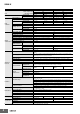
S8VK-X Power rating 240 W Rated output voltage Item Indication monitor Efficiency * Inrush current * 92% typ. 230 VAC input 93% typ. 93% typ. 94% typ. 94% typ. Single-phase, 85 to 264 VAC, 90 to 350 VDC, 265 to 300 VAC (1 second) 50/60 Hz (47 to 63 Hz) 50/60 Hz (47 to 63 Hz) 115 VAC input 2.4 A typ. 2.4 A typ. 4.6 A typ. 4.6 A typ. 230 VAC input 1.2 A typ. 1.2 A typ. 2.3 A typ. 2.3 A typ. 0.9 min. 115 VAC input 0.5 mA max. 230 VAC input 1 mA max. 115 VAC input 16 A typ.
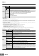
S8VK-X Standards Harmonic current emissions EMI Conforms to EN 61000-3-2 Conducted emissions Conforms to EN 61204-3 Class B, EN 55011 Class B Radiated emissions Conforms to EN 61204-3 Class B, EN 55011 Class B EMS Conforms to EN 61204-3 high severity levels Safety standards UL 508, ANSI/ISA 12.12.01 (Listing) (For 30 W, 60 W, and 90 W only Class 2 Output: Per UL 1310) CSA C22.2 No. 107.1, CSA C22.2 No. 213 (cUL) (For 30 W, 60 W, and 90 W only Class 2 Output: Per CSA C22.2 No.
S8VK-X Communication and Indication Items Communication * Indication monitor * Resolution Data update cycle Output voltage measurement Yes Yes 0.1 V 5 ms Measurement accuracy ±2% (percentage of output voltage value) ±1 digit Output current measurement Yes Yes 0.1 A 5 ms Measurement accuracy ±5% (percentage of rated output current) ±1 digit Peak hold current measurement Yes Yes 0.
S8VK-X Overload Protection Output voltage (V) When the load current reaches 121% to 160% of the rated current for S8VK-X03005-EIP, S8VK-X06012-EIP, S8VK-X06024-EIP, and S8VK-X12024@-EIP, 101% to 110% for S8VK-X09024@-EIP, or 151% to 165% for S8VK-X24024@-EIP and S8VK-X48024@-EIP, output voltage is automatically lowered to protect the Power Supply from short-circuit currents and overcurrents. When the output current falls within the rated range, the overload protection function is automatically cleared.
S8VK-X Module Status and Network Status Indicators Name Color Status Lit Green Module status Indicator (MS) Flashing Lit Red --- Not lit Green/Red Flashing Lit Flashing Red Voltage measurement abnormality, current measurement abnormality No power supply When power is turned ON Connection established Lit Network status Indicator (NS) --RAM abnormality, EEPROM abnormality Flashing Green Operating status Normal Connection not established Multiple IP addresses Flashing --- Not lit Green/Red
S8VK-X Peak Hold Current Years until replacement The output current maximum value is stored as the peak hold current. (5 ms average value) Measurement is not performed for approximately 3 seconds immediately after the input power is turned ON. (Indication monitor) is indicated at the time of purchase (when initially powered on), and continues to be indicated for approximately one month.
S8VK-X Difference between Expected Life and Replacement Time Total Run Time OMRON calculates the expected life based on the following conditions. The accumulated value of the product's time powered on is measured as the total run time. (With indication monitor) Total run time increases in (kh) steps with use. (Communication) Total run time increases in (h) steps with use. Time Chart 1.Rated input voltage 2. Load rate: 50% 3. Ambient temperature: +40°C 4.
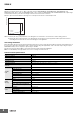
S8VK-X Connections Block Diagrams S8VK-X03005-EIP/06012-EIP/06024-EIP L1 L2 INPUT N1 +V1 Fuse 250 VAC 6.
S8VK-X S8VK-X24024@-EIP L1 L2 INPUT N1 +V1 Fuse 250 VAC 8.
S8VK-X Nomenclature With Indication Monitor 90 W/120 W 240 W 480 W S8VK-X09024A-EIP S8VK-X12024A-EIP S8VK-X24024A-EIP S8VK-X48024A-EIP ⑥⑦⑧⑨⑩ ⑥⑦⑧⑨⑩ ⑥⑦⑧⑨⑩ ⑪ ⑫ ⑭ ⑮ ⑯ ⑱ ⑲ ⑬ ⑰ ⑪ ⑫ ⑭ ⑮ ⑯ ⑱ ⑬ ⑲ ⑪ ⑫ ⑭ ⑮ ⑯ ⑱ ⑬ ⑲ ⑰ ⑰ ①②③④⑤ ①②③④⑤ ①②③④⑤ 30 W/60 W 90 W/120 W 240 W 480 W S8VK-X03005-EIP S8VK-X06012-EIP S8VK-X06024-EIP S8VK-X09024-EIP S8VK-X12024-EIP S8VK-X24024-EIP S8VK-X48024-EIP ⑥⑦⑧⑨⑩ ⑥⑦⑧⑨⑩ ⑥⑦⑧⑨⑩ ⑥⑦⑧⑨⑩ Without Indication Monitor ⑪ ⑫ ⑬ ⑯ ⑱ ⑲ ⑰ ⑪ ⑫ ⑯ ⑱ ⑲ ⑪ ⑫ ⑪ ⑫ ⑬ ⑰ ⑯ ⑱ ⑬ ⑲ ⑬ ⑲
S8VK-X No. Terminal name 1 L1 2 L2 3 N1 4 N2 5 PE 6 +V1 7 +V2 8 -V1 Name Function Input terminals Connect the input lines to these terminals. * 1 Protective Earth terminal (PE) Connect the ground line to this terminal. * 2 DC Output terminals Connect the load lines to these terminals. 9 -V2 10 -V3 11 --- Output indicator (DC ON: Green) The green indicator indicates when a DC voltage is being output.
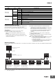
S8VK-X Engineering Data Derating Curves Horizontal separation: Less than 15 mm 120 Load ratio (%) Load ratio (%) Horizontal separation: 15 mm or more 100 75% 80 120 100 80 60 60 40 40 20 20 0 -40 -30 -20 -10 0 0 -40 -30 -20 -10 10 20 30 40 50 60 70 80 Ambient temperature (°C) 0 10 20 30 40 50 60 70 80 Ambient temperature (°C) Note: 1. 1%/V derating at less than 100 VAC 2. 0.5%/V derating at less than 140 VDC 3.
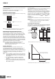
S8VK-X Dimensions (Unit: mm) Unit S8VK-X03005-EIP (30 W) S8VK-X06012-EIP (60 W) S8VK-X06024-EIP (60 W) 5.4 (2.3) 90±1 86 10 78.55 Rail stopper 90±1 5.4 40±1 3.5 4.7 (Sliding: 10 max.) The above diagram shows S8VK-X06024-EIP. S8VK-X09024@-EIP (90 W) S8VK-X12024@-EIP (120 W) 5.4 (2.3) 90±1 86 15 78.55 Rail stopper 90±1 5.4 55±1 4.7 (Sliding: 10 max.) 3.5 The above diagram shows S8VK-X09024A-EIP.
S8VK-X S8VK-X24024@-EIP (240 W) 121.4±1 38±1 5.4 (0.6) (2.3) 117 111.4 (4) 124±1 108.8 22 Rail stopper (0.6) 5.4 19.8 (10) 5.2 (Sliding: 8 max.) The above diagram shows S8VK-X24024A-EIP. S8VK-X48024@-EIP (480 W) 121.4±1 60±1 7.5 0.9 (0.6) (2.3) 117 111.4 (4) 124±1 108.8 22 Rail stopper The above diagram shows S8VK-X48024A-EIP. 18 5.4 19.8 (0.6) 5.2 (Sliding: 8 max.
S8VK-X Name Model number Dimensions Appearance 41 35 25 2-4.5 dia.±0.1 Front-mounting bracket (For 30 W and 60 W models) S82Y-VS10F 35±0.1 7.3 10 40 50 t = 1.0 Left-side mounting 3-4.5 dia.±0.1 Side-mounting bracket (For 30 W and 60 W models) Right-side mounting 60±0.1 80 S82Y-VS10S 55±0.1 35 13 64 t = 2.0 240 W Three locations Mounting screw tightening torque: 0.5 to 0.
S8VK-X Safety Precautions Warning Indications WARNING Indicates a potentially hazardous situation which, if not avoided, will result in minor or moderate injury, or may result in serious injury or death. Additionally, there may be significant property damage. CAUTION Indicates a potentially hazardous situation which, if not avoided, may result in minor or moderate injury or in property damage. Precautions for Safe Use Supplementary comments on what to do or avoid doing, to use the product safely.
S8VK-X Mounting (A) Standard (vertical) mounting • Use the following material for the wires after confirming the rating of the wires in order to prevent smoking or ignition. (B) Front, side-by-side mounting Recommended Wire Type Terminal Input Wiring • Connect the ground completely. A protective earthing terminal stipulated in safety standards is used. Electric shock or malfunction Output may occur if the ground is not connected completely. • Minor fire may possibly occur.
S8VK-X Power Boost Function Making Positive/Negative Outputs The boost current is a temporary current that exceeds the rated current. However, it should meet the following four boost current conditions.
S8VK-X S8VK-X +V INPUT IN 1 -V -V S8VK-X +V INPUT IN 2 -V S8VK-X +V INPUT Load +V IN 1 -V S8VK-R +V S8VK-R +V INPUT Backup operation is possible if you use two Power Supplies of the same model. Even if one Power Supply fails, operation can be continued with the other Power Supply. Make sure that the maximum load does not exceed the capacity of one Power Supply. Use the S8VK-R or connect external diodes. For backup operation with 30 W, 60 W, 90 W or 120 W Power Supplies, use the S8VK-R10.
S8VK-X Precautions for Correct Use DIN Rail Mounting 30 W/60 W/90 W/120 W To mount the Block on a DIN Rail, hook portion (A) of the Block onto the rail and press the Block in direction (B). 240 W/480 W To mounting on a DIN Rail, hook portion (A) of the Block onto the rail and press in the (B) direction. (A) Connecting Stranded Wires Use the following procedure to connect the wires to the terminal block. 1. Hold a flat-blade screwdriver at an angle and insert it into the release hole.
S8VK-X Recommended Ferrules and Crimping Tools Recommended Ferrules S8VK-X03005-EIP, X06012-EIP, X06024-EIP S8VK-X09024@-EIP, X12024@-EIP, X24024@-EIP : Input and Output Terminals S8VK-X48024@-EIP: Input Terminals Recommended Flat-blade Screwdriver Use a flat-blade screwdriver to connect and remove wires. Use the following flat-blade screwdriver. The following table shows manufacturers and models as of 2015/Dec. Side Front Applicable wire 2.5 mm dia.
S8VK-X In Case There Is No Output Voltage The possible cause for no output voltage may be that the overload protection or overvoltage protection has operated. The internal protection may operate if a large amount of surge voltage, such as a lightning inrush, is applied to the input. In case there is no output voltage, please check the following points before contacting us: Checking overload protected status: Check whether the load is in overload status or is short-circuited.
S8VK-X Period and Terms of Warranty Warranty Period The Power Supply warranty is valid for a period of Five years from the date of shipment from the factory. Terms of Warranty The warranty is valid only for the following operating conditions. 1. Average ambient operating temperature of the Power Supply: 40°C max. 2. Average load rate of 80% max. 3. Mounting method: Standard mounting Note: The maximum ratings must be within the derating curve.
Noise Filter S8V-NF (Single-phase 250 V 3 A / 6 A Type) DIN Rail Mounting Type Ideal for Control Panels Featuring a Slim Design that Saves Space Push-In Connections for Safe and Easy Wiring • 150 kHz to 1 MHz high attenuation • Operation possible at ambient temperatures from -40 to 85°C • Complies with RoHS directives • Certification for 3,000 m altitude (UL/EN 60939) • Five years Warranty *1 *1. Refer to “Period and Terms of Warranty” on page 36 for details. ! Refer to “Safety Precautions” on page 33.
S8V-NF Ratings and Characteristics Item Rated current Rated voltage Leakage current DC resistance I/O Attenuation characteristics Withstand voltage Insulation resistance Ambient operating temperature Derating start temperature Storage temperature Environment Ambient operating humidity Vibration resistance Shock resistance Weight Construction Degree of protection 3A 6A Single-phase 250 VAC 50/60 Hz *1, 250 VDC 1.0 mA max. (250 VAC/60 Hz) 110 mΩ max. 25 dB min. (Common Mode: 0.1 to 10 MHz, Normal Mode: 0.
S8V-NF Engineering Data Derating Curves S8V-NFS206 120 Load ratio (%) Load ratio (%) S8V-NFS203 100 120 100 80 80 60 60 40 40 20 20 50% 0 -40 -30 -20 -10 0 -40 -30 -20 -10 0 10 20 30 40 50 60 70 80 90 Operating temperature (°C) 0 10 20 30 40 50 60 70 80 90 Operating temperature (°C) Note: If using at an altitude of 2000 m to 3000 m, multiply the above derating curve by 0.8 to reduce the load.
S8V-NF Dimensions (Unit: mm) S8V-NFS203 S8V-NFS206 90 ±1 (1.2) 5.4 78.55 86 90 ±1 3.5 4.7 (Sliding: 10 max.) 5.4 32 ±1 Rail Stopper Mounting Brackets Name Model number Front-mounting bracket S82Y-VS10F Side-mounting bracket S82Y-VS10S Name Model number Dimensions Appearance 41 Front-mounting bracket 35 25 4.5 dia.±0.1 S82Y-VS10F 35±0.1 7.3 10 40 50 t = 1.0 Left-side mounting 4.5 dia.±0.1 60±0.1 80 Side-mounting bracket Right-side mounting S82Y-VS10S 55±0.
S8V-NF DIN Rails (Order Separately) (Unit: mm) Mounting Rail (Material: Aluminum) PFP-100N PFP-50N 7.3±0.15 4.5 35±0.3 15 25 10 25 25 1,000 (500) * 10 27±0.15 15 (5) * 25 1 * Values in parentheses are for the PFP-50N. Mounting Rail (Material: Aluminum) PFP-100N2 16 4.5 35±0.3 27 15 25 10 25 25 1,000 10 25 End Plate 24 15 29.2 1 1.5 10 PFP-M 6.2 M4×8 panhead screw 50 1.8 1 1.8 35.5 35.5 11.5 10 M4 spring washer 1.3 4.
S8V-NF Safety Precautions Warning Indications WARNING CAUTION Indicates a potentially hazardous situation which, if not avoided, will result in minor or moderate injury, or may result in serious injury or death. Additionally, there may be significant property damage. Indicates a potentially hazardous situation which, if not avoided, may result in minor or moderate injury or in property damage. Precautions for Safe Use Supplementary comments on what to do or avoid doing, to use the product safely.
S8V-NF Wiring • Connect the ground completely. A protective earthing terminal stipulated in safety standards is used. Electric shock or malfunction may occur if the ground is not connected completely. • When you insert wires or insert a screwdriver into a release hole, do not press down on the terminal block with a force of 40 N or greater. • Do not wire anything to the release holes. • Do not tilt or twist a flat-blade screwdriver while it is inserted into a release hole on the terminal block.
S8V-NF Checking Connections • After the insertion, pull gently on the wire to make sure that it will not come off and the wire is securely fastened to the terminal block • If you use a ferrule with a conductor length of 10 mm, part of the conductor may be visible after the ferrule is inserted into the terminal block, but the product insulation distance will still be satisfied. Removing Wires from the Push-In Plus Terminal Block Use the following procedure to remove wires from the terminal block.
S8V-NF Period and Terms of Warranty Warranty Period The product warranty is valid for a period of five years from the date of shipment from the factory. Terms of Warranty The warranty is valid only for the following operating conditions. 1. Average ambient operating temperature of the product: 40°C max. (See note.) 2. Average load rate of 80% max. (See note.) 3. Mounting method: Standard mounting Note: The maximum ratings must be within the derating curve.
Terms and Conditions Agreement Read and understand this catalog. Please read and understand this catalog before purchasing the products. Please consult your OMRON representative if you have any questions or comments. Warranties. (a) Exclusive Warranty. Omron’s exclusive warranty is that the Products will be free from defects in materials and workmanship for a period of twelve months from the date of sale by Omron (or such other period expressed in writing by Omron).
EtherNet/IPTM is the trademarks of ODVA. Modbus is a registered trademark of Schneider Electric. Other company names and product names in this document are the trademarks or registered rademarks of their respective companies. OMRON Corporation Industrial Automation Company Authorized Distributor: Kyoto, JAPAN Contact: www.ia.omron.com Regional Headquarters OMRON EUROPE B.V.