
Datasheet


S8VK-X
21
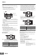
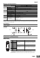
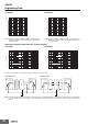
Mounting
Wiring
• Connect the ground completely. A protective earthing terminal
stipulated in safety standards is used. Electric shock or malfunction
may occur if the ground is not connected completely.
• Minor fire may possibly occur. Ensure that input and output
terminals are wired correctly.
• When you insert wires or insert a screwdriver into a release hole,
do not press down on the terminal block with a force of 40 N or
greater.
• Do not wire anything to the release holes.
• Do not tilt or twist a flat-blade screwdriver while it is inserted into a
release hole on the terminal block. The terminal block may be
damaged.
• Insert a flat-blade screwdriver into the release holes at an angle.
The terminal block may be damaged if you insert the screwdriver
straight in.
• Do not allow the flat-blade screwdriver to fall out while it is inserted
into a release hole.
• Do not bend a wire past its natural bending radius or pull on it with
excessive force. This may cause a wire to be broken.
• Do not insert more than one wire into each terminal insertion hole.
• Do not pre-solder the ends of the wires. Doing so will inhibit proper
connection.
• Be sure to remove the sheet covering the S8M for machining
before power-ON so that it does not interfere with heat dissipation.
• If there is a possibility of vibration or shock, please use wires and
stranded wires with ferrules.
• Use the following material for the wires after confirming the rating
of the wires in order to prevent smoking or ignition.
Recommended Wire Type
• Input crossover wiring can be used for the input side of this Power
Supply.
• Do not use crossover wiring for more than five Power Supplies,
and do not allow the steady-state current to the input terminals to
exceed 10 A. The above table gives the recommended wires for
one Power Supply.
• If you use crossover wiring for N number of Power Supplies, a
current that is N times the current for a standalone Power Supply
may flow to the input terminals.Take this into consideration when
you select wiring materials.
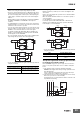
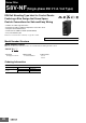
Stripping Length
S8VK-X03005-EIP, S8VK-X06012-EIP,
S8VK-X06024-EIP, S8VK-X09024@-EIP,
S8VK-X12024@-EIP, S8VK-X24024@-EIP
: Input and output terminals
S8VK-X48024@-EIP: Input terminals
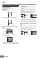
S8VK-X48024@-EIP: Output terminals
(A) Standard (vertical)
mounting
(B) Front, side-by-side
mounting
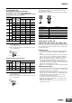
Terminal Model number
Recommended wire
gauge
(mm
2
) (AWG)
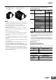
Input
S8VK-X03005-EIP,
X06012-EIP, X06024-EIP,
X09024@-EIP, X12024@-EIP
0.34 to 2.5 22 to 14
S8VK-X24024@-EIP 0.5 to 2.5 20 to 14
S8VK-X48024@-EIP 0.75 to 2.5 18 to 14
Output
S8VK-X03005-EIP 0.75 to 2.5 18 to 14
S8VK-X06012-EIP 0.75 to 2.5 18 to 14
S8VK-X06024-EIP 0.5 to 2.5 20 to 14
S8VK-X09024@-EIP 0.5 to 2.5 20 to 14
S8VK-X12024@-EIP 0.75 to 2.5 18 to 14
S8VK-X24024@-EIP 2 to 2.5 14
S8VK-X48024@-EIP 3.5 to 6 12 to 10
PE
(protective
earth)
terminal
S8VK-X03005-EIP,
X06012-EIP, X06024-EIP,
X09024@-EIP, X12024@-EIP,
X24024@-EIP, X48024@-EIP
2 to 2.5 14
Recommended wire
gauge
Stripping length
(Ferrules not used)
0.34 to 1.5 mm
2
/
AWG22 to 16
8 mm
2 to 2.5 mm
2
/AWG14 10 mm
Recommended wire
gauge
Stripping length
(Ferrules not used)
3.5 to 6 mm
2
/
AWG12 to 10
15 mm