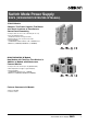
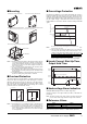
Switch Mode Power Supply S8VS (15/30/60/90/120/180/240-W Models) 15/30-W Models Compact, Thin Power Supplies That Mount Just About Anywhere to Contribute to Control Panel Downsizing • Compact, thin size: 22.5 × 85 × 96.5 mm (W × H × D). • Three mounting directions (standard, horizontal, facing horizontal). • Mounting directly onto the panel is possible. • Safety standards: UL508/60950-1/1604, CSA C22.2 No. 14/60950-1/213, EN50178 (= VDE0160), EN60950-1 (= VDE0805).
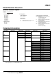
Model Number Structure ■ Model Number Legend S8VS- @@@@@@@ 1 2 3 3. Configuration 15-W, 30-W Models None: Standard 1. Power Ratings 015: 15 W 030: 30 W 060: 60 W 090: 90 W 120: 120 W 180: 180 W 240: 240 W 60-W Models None: Standard A: With maintenance forecast monitor B: With total run time monitor 2.
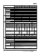
Specifications ■ Ratings/Characteristics Power ratings Type Item Efficiency (typical) Input Voltage Frequency Current 5-V models 12-V models 24-V models 100 V input 200 V input 230 V input Power factor Harmonic current emissions Leakage current 100 V input 200 V input 230 V input Inrush current 100 V input (See note 1.) 200 V input 230 V input Voltage adjustment range (See note 2.) Ripple Output 15 W Standard 72% min. (76% typ.) 74% min. (79% typ.) 77% min. (81% typ.
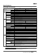
Specifications ■ Ratings/Characteristics Power ratings Type Standard Item Efficiency (typical) Input Voltage Frequency Current Output Additional functions 60 W Maintenance forecast monitor Total run time monitor Standard 90 W Maintenance forecast monitor Total run time monitor 78% min. (86% typ.) 80% min. (87% typ.) 100 to 240 VAC (85 to 264 VAC) 50/60 Hz (47 to 450 Hz) 100 V input 1.7 A max. 2.3 A max. 200 V input 1.0 A max. 1.4 A max. 230 V input (0.7 A typ.) (0.9 A typ.
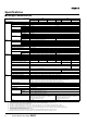
Power ratings Type 120 W 180 W Maintenanc Total run Standard Maintenanc Total run e forecast time e forecast time Item monitor monitor monitor monitor Efficiency (typical) 80% min. (87% typ.) 80% min. (88% typ.) Input Voltage 100 to 240 VAC (85 to 264 VAC) Frequency 50/60 Hz (47 to 63 Hz) Current 100 V input 1.9 A max. 2.9 A max. 200 V input 1.1 A max. 1.6 A max. 230 V input (0.6 A typ.) (0.9 A typ.) Power factor 0.95 min. Harmonic current emissions Conforms to EN61000-3-2 Leakage current 100 V input 0.
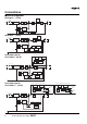
Connections ■ Block Diagrams S8VS-015@@ (15-W) Undervoltage indicator Fuse 2.5 A AC (L) INPUT +V DC OUTPUT Noise filter −V AC (N) Inrush current protection circuit Rectifier/ smoothing circuit Overvoltage protection Rectifier/ smoothing circuit Drive control circuit Voltage detection circuit Overcurrent detection circuit Photocoupler S8VS-030@@ (30-W) Undervoltage indicator Fuse 3.
Sinking type (S8VS-12024A, S8VS-12024B) S8VS-12024 (120-W) S8VS-12024@@ (120-W) Display circuit Sourcing type (S8VS-12024AP, S8VS-12024BP) Switch Display circuit Switch Alarm DC Low Alarm DC Low Arithmetic operation circuit Arithmetic operation circuit Yrs/kh Yrs/kh Rectifier/smoothing circuit Common Photocoupler Fuse 3.
Construction and Nomenclature (15-W, 30-W Models) ■ Nomenclature 15-W, 30-W Models S8VS-015@@/S8VS-030@@ 1 2 4 5 No. 1 2 3 4 5 6 Name AC Input terminals (L), (N) Protective Earth terminal (PE) DC Output terminals (−V), (+V) Output indicator (DC ON: Green) Undervoltage indicator (DC LOW: Red) Output voltage adjuster (V.ADJ) Function Connect the input lines to these terminals. (See note 1.) Connect the ground line to this terminal. (See note 2.) Connect the load lines to these terminals.
■ Overvoltage Protection Standard mounting with DIN rail Horizontal mounting with DIN rail Standard mounting with S82Y-VS30P Horizontal mounting with S82Y-VS30P Note: The Side-mounting Bracket can be mounted from either side. Consider the possibility of an overvoltage and design the system so that the load will not be subjected to an excessive voltage even if the feedback circuit in the Power Supply fails.
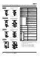
Construction and Nomenclature (60-W, 90-W, 120-W, 180-W, and 240-W Models) ■ Nomenclature 60-W Models Standard Model Models with Display Monitor S8VS-06024 S8VS-06024@ 1 2 1 2 6 7 8 4 5 4 5 3 3 Note: The S8VS-06024A is shown above. 90-W/120-W Models Standard Models Models with Display Monitor S8VS-09024/S8VS-12024 No. Name 1 AC Input terminals (L), (N) 2 Protective Earth terminal (PE) 3 DC Output terminals (−V), (+V) 4 Output indicator (DC ON: Green) 5 Output voltage adjuster (V.
Engineering Data (S8VS-@@@24@@ Only) ■ Mode Change S8VS-@@@24A@ Models (with display monitor) can display the output voltage, output current, peak hold current, or maintenance forecast monitor time. S8VS-@@@24B@ Models (with display monitor) can display the output voltage, output current, peak hold current, or total run time. Power-ON Model indication Operation mode Press and hold Up key U or Down Key D for three seconds or more. Press Mode key and hold for three seconds or more.
■ Peak Hold Current Reset ■ Multiple Alarms The peak value of the output current (i.e., the peak hold current) can be reset on the display. When two or more different alarms occur at the same time Operation Mode Operation mode Key Press 3 seconds or more. Undervoltage alarm Reset (See note.) Peak hold current value measurement starts 2 seconds (Peak hold current will be displayed 2 seconds after it is reset.) The indication shifts alternately in the direction of the arrow every 2 s.
■ Self-Diagnostics Function Numbers in the following table indicate the number used in Nomenclature on pages 8 and 10. (6) Main display Description Output status Restoration method Setting after restoration Noise detected in voltage or current No change Automatic restoration No change Overheated (12) Maintenance forecast output terminal (Yrs) turns OFF.
■ Maintenance Forecast (S8VS-@@@24A@) Displays when the maintenance forecast has reached the set value. Operation Mode The maintenance forecast has reached the set value. Maintenance forecast monitor (See note.) Remaining time until replacement Output voltage Note: This indicator alternately displays alarm ( ) and the maintenance time until replacement. Output current ■ Indication and Output When the product is purchased, “ful” will be indicated.
■ Maintenance Forecast Monitor Function The Power Supply is equipped with electrolytic capacitors. The electrolyte inside the electrolytic capacitor penetrates the sealing rubber and evaporates as time passes since it is manufactured, which causes deterioration of characteristics such as decreasing the capacitance, etc. Due to this deterioration of the characteristics of the electrolytic capacitor, the Power Supply decreases its performance as time passes.
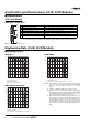
■ Models with Total Run Time Monitor (S8VS-@@@24B@) S8VS-06024B Example: Alarm Displays When a Total Run Time Set Value of 88 kh Is Reached The accumulated value of the operating time of the Power Supply is displayed as the total run time. 0 (kh) will be displayed initially after purchase and then the display will advance in 1-kh steps as the operating time accumulates. The S8VS-06024B, however, does not have an alarm function (setting, display, or output).
Engineering Data (60-W, 90-W, 120-W, 180-W, 240-W Models) Load (%) ■ Derating Curve ■ Overvoltage Protection 120 1 100 See note 1. 80 Output voltage (V) 60 40 20 0 −20 −10 0 10 20 30 40 50 Consider the possibility of an overvoltage and design the system so that the load will not be subjected to an excessive voltage even if the feedback circuit in the Power Supply fails. When an excessive voltage that is approximately 130% of the rated voltage or more is output, the output voltage is shut OFF.
■ Undervoltage Alarm Function (Indication and Output) (S8VS-@@@24@@ Only) When output voltage drop is detected, an alarm (a01) and lowest output voltage value are indicated alternately. The preset value of detection voltage can be changed in the setting mode. (From 18.5 to 27.5 V (18.5 to 26.3 V for the S8VS-24024@@), in 0.1V steps. The value is fixed at 20.0 V for the S8VS-06024@.
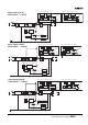
Dimensions Note: All units are in millimeters unless otherwise indicated. S8VS-015@@ (15-W) S8VS-030@@ (30-W) 4.8 (Sliding: 10 max.) 35.2 85 4 4.8 (Sliding: 10 max.) 22.5 96.4 Note: The illustration is the S8VS-03024 Model. S8VS-06024 (60-W) S8VS-06024@ (60-W) 11.3 Five, M4 with square washer 10 97 35.4 95 74 1 40 108.3 Track stopper 4.5 (Sliding: 15 max.) Note: The illustration is the S8VS-06024A Model. S8VS-09024 (90-W)/S8VS-12024 (120-W) S8VS-09024@@ (90-W)/S8VS-12024@@ (120-W) 10.
S8VS-24024 (240-W) S8VS-24024@@ (240-W) Seven, M4 with square washer 125.3 100 120.3 94 34.9 115 10 50 Track stopper 4.5 (Sliding: 15 max.) Track stopper Note: The illustration is the S8VS-24024A Model. ■ DIN Rail (Order Separately) Note: All units are in millimeters unless otherwise indicated. Mounting Rail (Material: Aluminum) PFP-100N PFP-50N 7.3±0.15 4.5 35±0.3 15 25 10 25 25 25 10 1,000 (500) * 27±0.15 15(5) * 1 *Values in parentheses are for the PFP-50N.
■ Mounting Brackets Name Model Side-mounting Bracket (for 15- and 30-W models) S82Y-VS30P Side-mounting Bracket (for 60-, 90-, and 120-W models) S82Y-VS10S Side-mounting Bracket (for 180-W models) S82Y-VS15S Side-mounting Bracket (for 240-W models) S82Y-VS20S Front-mounting Bracket (for 60-, 90-, 120-, 180-, and 240-W models) (See note.) S82Y-VS10F Note: Two required to mount a 240-W model. Type Side-mounting Bracket (For 15-, 30-W models) Model Dimensions Appearance S82Y-VS30P 0.5 7.1 109.
Safety Precautions !CAUTION Minor electric shock, fire, or Product failure may occasionally occur. Do not disassemble, modify, or repair the Product or touch the interior of the Product. Minor burns may occasionally occur. Do not touch the Product while power is being supplied or immediately after power is turned OFF. Fire may occasionally occur. Tighten terminal screws to the specified torque (15 and 30 W Models: 0.8 to 1.0 N·m 60, 90,120, 180, and 240 W Models: 1.08 N·m).
Do not use the Power Supply in locations subject to direct sunlight. Do not use locations where liquids, foreign matter, or corrosive gases may enter the interior of products. S8VS-@@@24A@ Models only Satisfy the following conditions when storing the Power Supply for long periods of time to maintain its remaining service life function. • When storing for more than three months, store within an ambient temperature range of −25 to +30°C and the humidity range of 25% to 70%.
DIN Rail Mounting In Case There Is No Output Voltage To mount the Block on a DIN rail, hook portion (A) of the Block onto the rail and press the Block in direction (B). The possible cause for no output voltage may be that the overcurrent or overvoltage protection has operated. The internal protection may operate if a large amount of surge voltage such as a lightening surge occurs while turning ON the power supply.
Switch Mode Power Supply S8VS 25
Switch Mode Power Supply S8VS
Switch Mode Power Supply S8VS 27
Warranty and Application Considerations Read and Understand this Catalog Please read and understand this catalog before purchasing the products. Please consult your OMRON representative if you have any questions or comments. Warranty and Limitations of Liability WARRANTY OMRON's exclusive warranty is that the products are free from defects in materials and workmanship for a period of one year (or other period if specified) from date of sale by OMRON.