New Product Switch Mode Power Supply S8VS (15/30/60/90/120/180/240/480-W Models) 60/90/120/180/240/480-W Models New Models with Indication Monitor and Simple Functions for Easy System Commissioning • New 90-W models with indication monitor that conform to UL Class 2 Output standards. • New models with screwless terminal blocks and indication monitor. • Status displayed on 3-digit, 7-segment display. • Safety standards: UL 508/60950-1, CSA C22.2 No. 107.
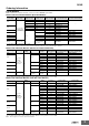
S8VS Model Number Structure Model Number Legend Note: Not all combinations are possible. Refer to List of Models in Ordering Information, below. S8VS- @@@@@@@@-@ 1 2 3 4 5 6 1. Power Ratings 015: 15 W 030: 30 W 060: 60 W 090: 90 W 120: 120 W 180: 180 W 240: 240 W 480: 480 W 2. Output voltage 05: 5 V 12: 12 V 24: 24 V 3.
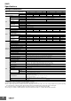
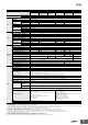
S8VS Ordering Information List of Models Note: For details on normal stock models, contact your nearest OMRON representative. Models without Indication Monitor (Standard Models) Power ratings Input voltage 15 W 30 W 60 W Output voltage Output current UL Class 2 Output standards Model number (screw terminal block) Model number (screwless terminal block) 5V 2.0 A Yes S8VS-01505 *1 12 V 1.2 A Yes S8VS-01512 24 V 0.65 A Yes S8VS-01524 5V 4.0 A Yes S8VS-03005 *2 2.
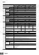
S8VS Specifications Ratings/Characteristics Power ratings Item Efficiency 12 V 24 V 5V 12 V 24 V With 100-VAC input 74% typical 79% typical 83% typical 74% typical 81% typical 85% typical With 200-VAC input 73% typical 78% typical 80% typical 74% typical 80% typical 86% typical 100 to 240 VAC (allowable range: 85 to 264 VAC, 80 to 370 VDC *5) Frequency *1 Current Additional functions Other 0.45 A max., 0.34 A typical 0.9 A max., 0.66 A typical With 200-VAC input 0.25 A max., 0.
S8VS Power ratings Item Efficiency Output Additional functions Other Standard Maintenance forecast monitor 83% typical 83% typical 83% typical 83% typical 85% typical 84% typical 85% typical Total run time monitor 100 to 240 VAC (allowable range: 85 to 264 VAC or 80 to 370 VDC *11) 50/60 Hz (47 to 450 Hz) With 100-VAC input 1.7 A max., 1.3 A typical 1.7 A max., 1.3 A typical 2.3 A max., 1.9 A typical 2.3 A max., 1.9 A typical With 200-VAC input 1.0 A max., 0.68 A typical 1.0 A max., 0.
S8VS Power ratings Item Type Efficiency 84% typical 83% typical 85% typical 85% typical 87% typical 85% typical 88% typical 87% typical 50/60 Hz (47 to 63 Hz) With 100-VAC input 1.9 A max., 1.5 A typical 2.9 A max., 2.2 A typical With 200-VAC input 1.1 A max., 0.71 A typical 1.6 A max., 1.1 A typical Output Additional functions Other Conforms to EN61000-3-2 With 100-VAC input 0.5 mA max. With 200-VAC input 1.0 mA max. With 100-VAC input 17.5 A max.
S8VS Power ratings Item Type Efficiency 88% typical 85% typical 89% typical 100 to 240 VAC (allowable range: 85 to 264 VAC or 80 to 370 VDC *11) 100 to 240 VAC (allowable range: 85 to 264 VAC) 50/60 Hz (47 to 63 Hz) 3.8 A max., 2.9 A typical 7.4 A max., 5.8 A typical With 200-VAC input 2.0 A max., 1.5 A typical 3.9 A max., 2.8 A typical Power factor 0.9 min. 0.95 min.
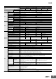
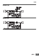
S8VS Connections Block Diagrams S8VS-015@@ (15 W) AC (L) Undervoltage indicator Fuse: 3.15 A INPUT +V DC output Noise filter −V AC (N) Rectifier Inrush Smoothing current circuit protection Rectifier/ smoothing circuit Drive control circuit Voltage detection circuit Overcurrent detection circuit Overvoltage detection circuit Photocoupler S8VS-030@@ (30 W) AC (L) INPUT Undervoltage indicator Fuse: 4.
S8VS S8VS-06024A-@ (60 W) S8VS-06024B-@ (60 W) Display circuit Switch Arithmetic operation circuit AC (L) Fuse 6.3 A INPUT Rectifier/smoothing circuit +V Noise filter DC OUTPUT AC (N) Rectifier Inrush Rectifier/ current protection smoothing circuit circuit −V Rectifier/smoothing circuit Drive control circuit Overcurrent circuit Current detection circuit Voltage detection circuit Overvoltage detection circuit Photocoupler S8VS-06024-@ (60 W) AC (L) INPUT Fuse 6.
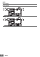
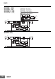
S8VS S8VS-09024A@-@ (90 W) S8VS-09024B@-@ (90 W) S8VS-09024BE-@ (90 W) S8VS-09024A@S-@ (90 W) S8VS-09024B@S-@ (90 W) S8VS-09024BES-@ (90 W) Sinking type (S8VS-09024A-@, S8VS-09024B-@, S8VS-09024AS-@, S8VS-09024BS-@) Sourcing type (S8VS-09024AP-@, S8VS-09024BP-@, S8VS-09024APS-@, S8VS-09024BPS-@) Type with no alarm output (S8VS-09024BE-@, S8VS-09024BES-@) Switch Display circuit Alarm DC Low Arithmetic operation circuit Yrs/kh Common Rectifier/smoothing circuit Photocoupler Fuse 8.
S8VS S8VS-12024A@-@ (120 W) S8VS-12024B@-@ (120 W) S8VS-12024BE-@ (120 W) Sinking type (S8VS-12024A-@, S8VS-12024B-@) Sourcing type (S8VS-12024AP-@ S8VS-12024BP-@) Type with no alarm output (S8VS-12024BE-@) Display circuit Switch Alarm DC Low Arithmetic operation circuit Yrs/kh Common Rectifier/smoothing circuit Photocoupler Fuse 5.
S8VS S8VS-18024A@-@ (180 W) S8VS-18024B@-@ (180 W) S8VS-18024BE-@ (180 W) Sinking type (S8VS-18024A-@, S8VS-18024B-@) Sourcing type (S8VS-18024AP-@, S8VS-18024BP-@) Type with no alarm output (S8VS-18024BE-@) Display circuit Switch Alarm DC Low Arithmetic operation circuit Yrs/kh Common Rectifier/smoothing circuit Photocoupler Fuse 6.
S8VS S8VS-24024A@-@ (240 W) S8VS-24024B@-@ (240 W) S8VS-24024BE-@ (240 W) Sinking type (S8VS-24024A-@, S8VS-24024B-@) Sourcing type (S8VS-24024AP-@, S8VS-24024BP-@) Type with no alarm output (S8VS-24024BE-@) Display circuit Switch Alarm DC Low Arithmetic operation circuit Yrs/kh Common Rectifier/smoothing circuit Photocoupler +V Fuse 8.
S8VS S8VS-48024-@ (480 W) S8VS-48024A-@ (480 W) S8VS-48024B-@ (480 W) +V +V Fuse 12A AC (L) INPUT +V Noise filter DC OUTPUT −V −V AC (N) Inrush current protection circuit Rectifier Harmonic current suppression (power factor improvement) Rectifier/ smoothing circuit Smoothing circuit −V Overvoltage detection circuit Control circuit Drive circuit Voltage detection circuit Arithmetic operation circuit Current detection circuit Overcurrent circuit Auxiliary power supply circuit Rectifier/ smoot
S8VS Construction and Nomenclature Nomenclature 15-W, 30-W Models S8VS-015@@/S8VS-030@@ 1 2 4 5 6 No. 1 2 3 4 5 6 Name Input terminals (L), (N) Protective Earth terminal (PE) DC Output terminals (−V), (+V) Output indicator (DC ON: Green) Undervoltage indicator (DC LOW: Red) Output voltage adjuster (V.ADJ) Function Connect the input lines to these terminals. *1 Connect the ground line to this terminal. *2 Connect the load lines to these terminals. Lights while a direct current (DC) output is ON.
S8VS Nomenclature 60-W Models No. Standard Model Models with Indication Monitor S8VS-06024 S8VS-06024@ 1 2 1 2 6 7 4 5 3 Function 1 Connect the input lines to these terminals. *1 2 Protective Earth terminal (PE) Connect the ground line to this terminal. *2 3 DC Output terminals (−V), (+V) Connect the load lines to these terminals. 4 Output indicator (DC ON: Green) Lights while a direct current (DC) output is ON. 5 Output voltage adjuster (V.ADJ) Use to adjust the voltage.
S8VS 480-W Models No. Standard Model 2 1 2 Protective Earth terminal (PE) Connect the ground line to this terminal. *2 3 DC Output terminals (−V), (+V) Connect the load lines to these terminals. 4 Output indicator (DC ON: Green) Lights while a direct current (DC) output is ON. 5 Output voltage adjuster (V.ADJ) Use to adjust the voltage. 6 Main display (Red) *3 Indicates the measurement or set value.
S8VS Engineering Data Derating Curve 60, 90, 120, 180, 240, and 480 W Load (%) Load ratio (%) 15 W 120 100 1 120 1 100 * 80 80 *1 60 60 *2 40 40 *3 20 20 0 −20 −10 0 0 −20 −10 0 10 20 *1 Standard mounting *2 Face-up mounting *3 Horizontal mounting 30 W Load ratio (%) 120 100 1 80 *1 60 *2 40 20 0 −20 −10 0 10 20 30 40 50 60 70 80 Ambient temperature (°C) *1 Standard mounting *2 Face-up mounting/Horizontal mounting Load ratio (%) 30
S8VS The load and the power supply are automatically protected from overcurrent damage by this function. Overload protection is activated if the output current rises above 105% of the rated current. When the output current returns within the rated range overload protection is automatically cleared. Face-up mounting with DIN rail Standard mounting with DIN rail Standard mounting with S82Y-VS30P Face-up mounting with S82Y-VS30P Note: The Side-mounting Bracket can be mounted from either side.
S8VS Overvoltage Protection Output voltage (V) Consider the possibility of an overvoltage and design the system so that the load will not be subjected to an excessive voltage even if the feedback circuit in the Power Supply fails. If an excessive voltage that is approximately 130% of the rated voltage (but approximately 110% of the rated voltage for the S8VS-09024@@@S) or more is output, the output voltage is shut OFF.
S8VS Dimensions Power Supplies with Screw Terminal Blocks Note: All units are in millimeters unless otherwise indicated. S8VS-015@@ (15 W) S8VS-030@@ (30 W) 8 4.8 (Sliding: 10 max.) 10.4 Five, M3.5 Square Washer Screw 35.2 85±1 4 Rail Stopper 96.4±1 4.8 (Sliding: 10 max.) 10.2 22.5±1 Note: The illustration is the S8VS-03024 model. S8VS-06024 (60 W) S8VS-06024A (60 W) S8VS-06024B (60 W) 97.1 12 max. 7 Five, M4 Square Washer Screw 35.4 74 Rail Stopper 103.3 95±1 10 4.
S8VS Seven, M4 Square Washer Screw S8VS-24024 (240 W) S8VS-24024A@ (240 W) S8VS-24024B@ (240 W) S8VS-24024BE (240 W) 100±1 117.6 8 max. 35.4 7 115±1 94 10 120.2 1 Rail Stopper 4.5 (Sliding: 15 max.) Rail Stopper 50 Screw Lessly Terminal (The 2.5 mm pace) Note: The illustration shows the S8VS-24024A model. S8VS-48024 (480 W) S8VS-48024A (480 W) S8VS-48024B (480 W) Nine, M4 Square Washer Screw 35.4 150±1 7 127.2±1 94 115±1 10 122.2 4.5 (Sliding: 15 max.
S8VS S8VS-18024-F (180 W) S8VS-18024A@-F (180 W) S8VS-18024B@-F (180 W) S8VS-18024BE-F (180 W) 116.6 10 8 max. 35.4 115±1 97.3 119.3 4.5 (Sliding: 15 max.) 75±1 1 Rail Stopper Note: The illustration shows the S8VS-18024-F model. S8VS-24024-F (240 W) S8VS-24024A@-F (240 W) S8VS-24024B@-F (240 W) S8VS-24024BE-F (240 W) 117.6 10 7 max. 35.4 100±1 115±1 97.3 10 119.3 4.5 (Sliding: 15 max.) 50 1 Rail Stopper Rail Stopper Note: The illustration shows the S8VS-24024-F model.
S8VS DIN Rail (Order Separately) Note: All units are in millimeters unless otherwise indicated. Mounting Rail (Material: Aluminum) PFP-100N PFP-50N 7.3±0.15 4.5 35±0.3 15 25 10 25 25 10 1,000 (500) * 25 27±0.15 15(5) * 1 * Values in parentheses are for the PFP-50N. Mounting Rail (Material: Aluminum) PFP-100N2 16 4.5 35±0.3 27 15 25 10 25 25 10 1,000 End Plate 25 15 24 29.2 1 1.5 PFP-M 10 6.2 M4×8 panhead screw 1.8 1 50 1.8 35.5 35.5 11.5 10 M4 spring washer 1.3 4.
S8VS Mounting Brackets Name Model Side-mounting Bracket (for 15- and 30-W models) S82Y-VS30P Side-mounting Bracket (for 60-, 90-, and 120-W models) S82Y-VS10S Side-mounting Bracket (for 180-W models) S82Y-VS15S Side-mounting Bracket (for 240-W models) S82Y-VS20S Front-mounting Bracket (for 60-, 90-, 120-, 180-, and 240-W models) * Note: Brackets cannot be used for 480-W models. * Two required to mount a 240-W model. Type Model S82Y-VS10F Dimensions 0.5 Appearance 7.1 109.4±0.1 3.5 dia. 85.
S8VS Display and Alarm Output Functions and Operating Procedures S8VS-@@@24A@@ models (with display monitor) can display the output voltage, output current, peak hold current, or maintenance forecast monitor time. S8VS-@@@24B@@/S8VS-@@@24BE@ models (with display monitor) can display the output voltage, output current, peak hold current, or total run time. Mode Change Power-ON Model indication Operation mode Press and hold Up key U or Down Key D for three seconds or more.
S8VS Peak Hold Current Reset Multiple Alarms The peak value of the output current (i.e., the peak hold current) can be reset on the display. When two or more different alarms occur at the same time Operation Mode Operation mode Key Press 3 seconds or more. Undervoltage alarm Reset (See note.) Peak hold current value measurement starts 2 seconds (Peak hold current will be displayed 2 seconds after it is reset.) The indication shifts alternately in the direction of the arrow every 2 s.
S8VS Self-Diagnostics Function Numbers in the following table indicate the number used in Nomenclature on pages 15 and 17. (6) Main display --- Description Output status Restoration method Setting after restoration Noise detected in voltage or current No change Automatic reset. No change h\t Overheated Maintenance forecast output terminal (Yrs) turns OFF. Automatic reset.
S8VS Maintenance Forecast (S8VS-@@@24A@@) Displays when the maintenance forecast has reached the set value. Operation Mode The maintenance forecast has reached the set value. Maintenance forecast monitor Output current Peak-hold current When the Product is purchased, “ful” will be indicated. As electrolytic capacitors deteriorate, indication changes to “hlf” (Refer to page 30).
S8VS Maintenance Forecast Monitor Function The Power Supply is equipped with electrolytic capacitors. The electrolyte inside the electrolytic capacitor penetrates the sealing rubber and evaporates as time passes since it is manufactured, which causes deterioration of characteristics such as decreasing the capacitance, etc. Due to this deterioration of the characteristics of the electrolytic capacitor, the Power Supply decreases its performance as time passes.
S8VS Models with Total Run Time Monitor (S8VS-@@@24B@@/S8VS-@@@24BE@) S8VS-06024B The accumulated value of the operating time of the Power Supply is displayed as the total run time. 0 (kh) will be displayed initially after purchase and then the display will advance in 1-kh steps as the operating time accumulates. The S8VS-06024B, however, does not have an alarm function (setting, display, or output).
S8VS Safety Precautions !CAUTION Minor electric shock, fire, or Product failure may occasionally occur. Do not disassemble, modify, or repair the Product or touch the interior of the Product. Minor burns may occasionally occur. Do not touch the Product while power is being supplied or immediately after power is turned OFF. Fire may occasionally occur. Tighten terminal screws to the specified torque (15- and 30-W models: 0.8 to 1.0 N·m/60-, 90-,120-, 180-, 240-, and 480-W models: 1.08 N·m).
S8VS • Strip I/O wires for 11 mm when using a screwless terminal block. * The rated current for output terminals is 10 A per terminal. Be sure to use multiple terminals simultaneously for current that exceeds the terminal rating. When applying a current of 10 A or more, use at least two terminals each for the positive and negative wires. 60-, 90-, 120-, 180-, 240-W Models Installation Environment • Do not use the Power Supply in locations subject to shocks or vibrations.
S8VS +V +V INPUT Load • The output voltage adjuster (V.ADJ) may possibly be damaged if it is turned with unnecessary force. Do not turn the adjuster with excessive force. • After completing output voltage adjustment, be sure that the output capacity or output current does not exceed the rated output capacity or rated output current. However, use the lower of the two maximum rated output currents as the current to the loads.) −V 0V Load Output Voltage Adjuster (V.
S8VS • Type: Schottky barrier diode • Dielectric strength (VRRM): Rated Power Supply output voltage or higher • Forward current (IF): Twice the rated Power Supply output current or higher • Increase the output voltage setting of Power Supply A and Power Supply B by the drop in the forward voltage (VF) of diodes D1 and D2. Also, the diodes will cause a power loss equivalent to the Power Supply output current (IOUT) times the diode forward voltage (VF).
MEMO 36
Terms and Conditions Agreement Read and understand this catalog. Please read and understand this catalog before purchasing the products. Please consult your OMRON representative if you have any questions or comments. Warranties. (a) Exclusive Warranty. Omron’s exclusive warranty is that the Products will be free from defects in materials and workmanship for a period of twelve months from the date of sale by Omron (or such other period expressed in writing by Omron).
OMRON Corporation Industrial Automation Company Authorized Distributor: Kyoto, JAPAN Contact: www.ia.omron.com Regional Headquarters OMRON EUROPE B.V. Wegalaan 67-69, 2132 JD Hoofddorp The Netherlands Tel: (31)2356-81-300/Fax: (31)2356-81-388 OMRON ELECTRONICS LLC 2895 Greenspoint Parkway, Suite 200 Hoffman Estates, IL 60169 U.S.A. Tel: (1) 847-843-7900/Fax: (1) 847-843-7787 OMRON ASIA PACIFIC PTE. LTD. No.